StudentAid
Unit 14: Light — Long Questions
10th Class Physics · Unit 14: Light
Reflection of light
- Reflection of light takes place when light hits a surface and bounces back instead of passing through. This usually occurs on smooth and shiny surfaces, such as mirrors.
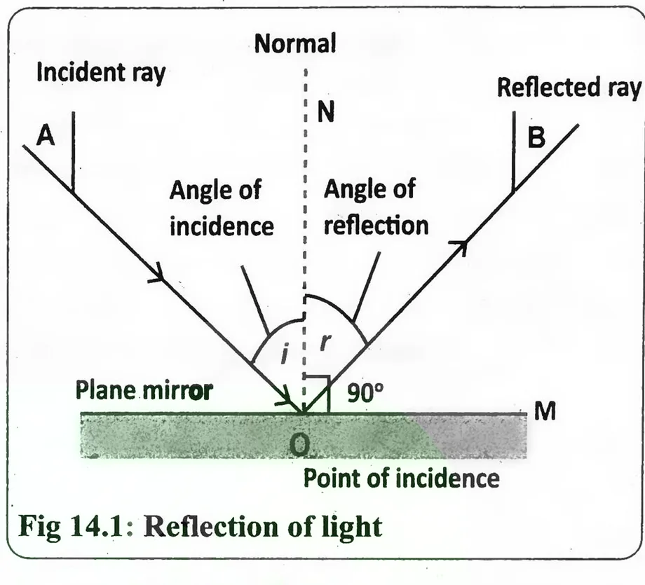
- The angle at which light strikes the surface (angle of incidence) is always equal to the angle at which it reflects (angle of reflection) (Fig 14.1).
1. Types of Reflection
There are two types of reflection:
a. Regular/Specular Reflection: It takes place on smooth surfaces (like mirrors) where light reflects in one direction, forming a clear image.
b. Diffused/Irregular Reflection: It occurs on rough surfaces (like paper), where light scatters in different directions, so no clear image is seen. Reflection is important for mirrors, periscopes, and optical devices, allowing us to see objects and form images.
2. Laws of Reflection
The reflection of light follows two basic laws:
a. First Law: The incident ray, the reflected ray, and the normal (a line drawn perpendicular to the surface at the point of reflection) all lie in the same plane.
b. Second Law: The angle of incidence (i) is always equal to the angle of reflection (r).
∠i = ∠r ................. (14.1)
c. Applications of Laws
These laws apply to all reflective surfaces, such as mirrors and water, and help us to understand how light bounces back to form images.
Finding the Image Position in a Plane Mirror
1. Objective
To observe and understand the position and characteristics of the image formed by a plane mirror.
2. Materials Needed
A plane mirror, an object, a measuring tape, a light source, and a white paper.
3. Procedure
- Place the plane mirror in an upright (vertical) position. Position the object in front of the mirror. Ensure the object is not taller than the mirror.
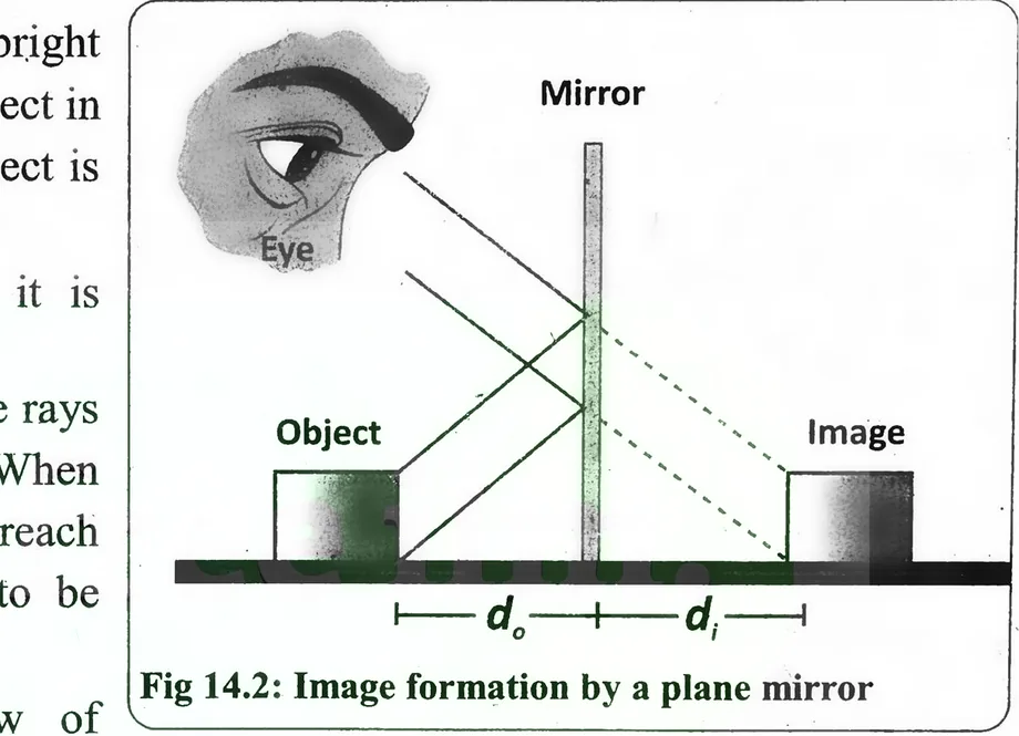
- Shine light onto the object, so it is clearly visible (Fig.14.2).
- Look at the mirror and observe the rays of light reflecting from the object. When two rays reflect off the mirror and reach the observer's eye, they appear to be coming from behind the mirror.
- By using a ruler and the law of reflection, we can draw the reflected rays on paper.
- Extend these reflected rays backward with dotted lines where they meet behind the mirror is the position of the image.
- This method shows the virtual image location.
4. Properties of Image Formed by Plane Mirror
There are four properties of an image formed by a plane mirror
a. The image is erect – It appears upright, just like the object.
b. The image is of the same size – The size of the image is exactly equal to the size of the object. It can be written as: d₁ = d₀
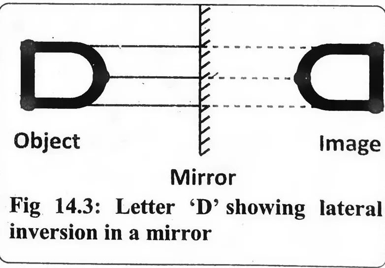
c. The image is laterally inverted – The left and right sides of the object appear reversed in the image as shown in Fig.(14.3).
d. The image is virtual – It cannot be captured on a screen because it is formed behind the mirror where light rays do not actually meet.
Refraction of Light
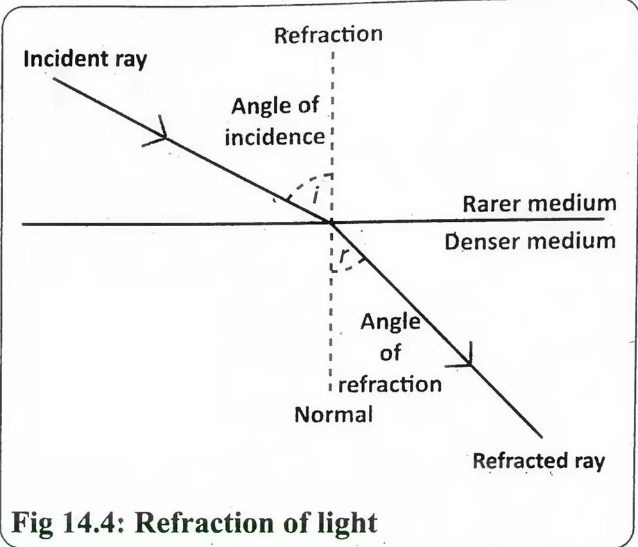
Definition "Refraction of light occurs when light changes direction as it passes from one medium to another, such as from air to water or glass (Fig. 14.4)."
Explanation
- This happens because light travels at different speeds in different materials.
- When light moves from a rarer medium (air) to a denser medium (glass or water), it bends towards the normal.
- When it moves from a denser medium to a rarer medium, it bends away from the normal.
- The amount of bending depends on the refractive index of the medium.
- Refraction explains many everyday phenomena, such as a pencil appearing bent in water, the working of lenses in glasses and cameras, and the formation of rainbows.
Laws of Refraction of Light
The bending of light during refraction follows two essential principles:
a. First Law: The incident ray, refracted ray, and the normal at the point of incidence where light enters a new medium all lie in the same plane.
b. Second Law (Snell's Law): The ratio of the sine of the angle of incidence i to the sine of the angle of refraction r remains constant for a specific pair of media.
sin i / sin r = n ................. (14.2)
Here, n is the refractive index of the second medium relative to the first. The refractive index indicates how much light bends when entering a different medium.
Speed of Light in a Medium
- The speed of light varies depending on the medium through which it travels.
- In vacuum, light moves at its maximum speed of 3 × 10⁸ m s⁻¹. However, when light passes through materials like air, water, or glass, it slows down due to interactions with medium particles.
- The denser the medium, the slower the speed of light.
- This change in speed is measured using the refractive index n, which is the ratio of the speed of light in vacuum to its speed in a given medium.
- The variation in the speed of light, when it moves between different material, is what causes refraction, or the bending of light.
Refractive Index
Definition "It is defined as the ratio of the speed of light in air or vacuum 'c' to the speed of light in the given medium 'V'."
1. Mathematically
Refractive index = Speed of light in air / Speed of light in medium
Or
n = c/v ................. (14.3)
2. Explanation
- The refractive index n of a medium is a measure of how much the speed of light changes when it enters that medium.
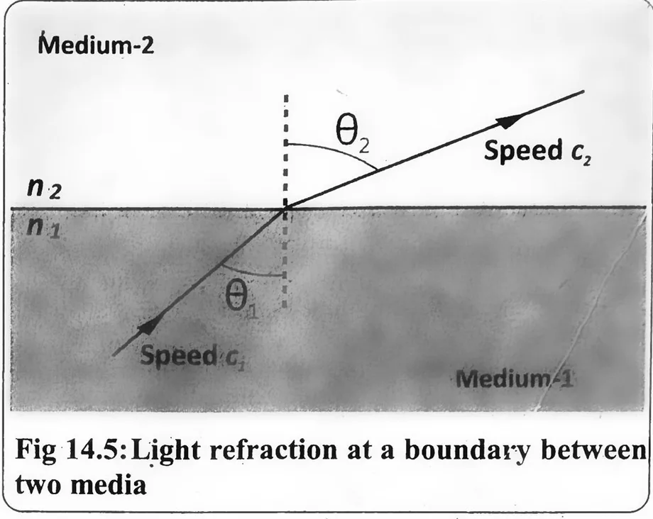
- The figure (14.5) illustrates how a light ray changes direction when passing from medium-1 (with refractive index n₁ and speed c₁) to medium-2 (with refractive index n₂ and speed c₂).
- The angles θ₁ (angle of incidence) and θ₂ (angle of refraction) demonstrate how the light bends according to Snell's law due to the difference in refractive indices.
Refraction Through Prism
Definition "A prism is a transparent optical object with at least two polished plane surfaces inclined towards each other."
Explanation
- It is usually made of optical glass and is used to refract (bend) light.
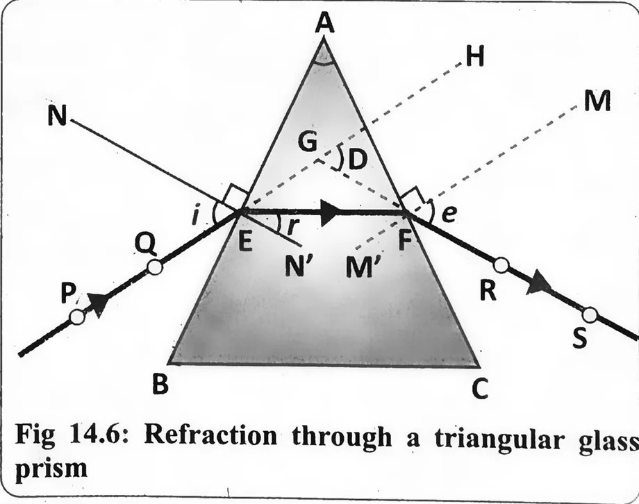
- In the case of a triangular prism (Fig. 14.6), 60° angle each.
- The light passing through it does not emerge parallel to its original path but instead changes direction.
- When an incident ray (PE) strikes the prism at point E, it bends towards the normal N and travels inside the prism as refracted ray (EF).
- Inside the prism, the ray makes an angle of refraction r before reaching the second surface at point F.
- As it exits the prism, it bends again, forming an emergent ray (FS) at an angle e.
- The emergent ray (FS) is not parallel to the incident ray (PE) but is instead deviated by an angle D, known as the angle of deviation.
- This bending effect of light through a prism is widely used in optical instruments, spectrometry, and light dispersion experiments.
Critical Angle
Definition "The angle of incidence for which the angle of refraction is 90° is called the critical angle."
Explanation
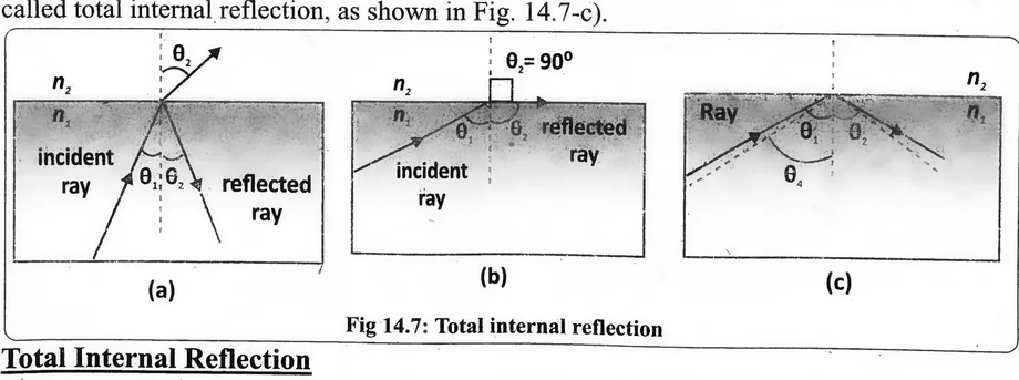
When a light ray is incident at a boundary between two different media, it splits into two parts: one part reflects back into the original medium (reflected ray), and the other part passes into the second medium (transmitted or refracted ray), as shown in Fig. (14.7-a).
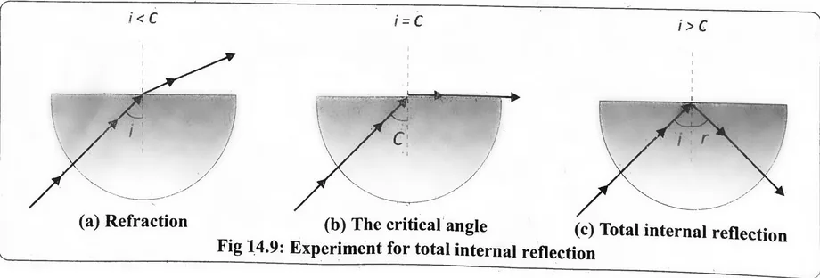
If the angle of incidence increases, then refraction angle also increases. The more the angle of incidence increases, the greater the angle of refraction becomes. At a particular angle, the refracted ray no longer enters the second medium but travels along the boundary. This angle is called the critical angle (Fig.14.7-b), and is defined as:
Now, if the angle of incidence is increased beyond the critical angle, the light ray does not refract at all. Instead, it reflects entirely back into the same medium. This phenomenon is called total internal reflection, as shown in Fig. 14.7-c).
Total Internal Reflection
Definition "Total internal reflection is the phenomenon of reflection of light ray back to the same medium when passing from denser medium to rarer medium in such a way that angle of incidence is greater than its critical angle."
Experiment to Study Refraction
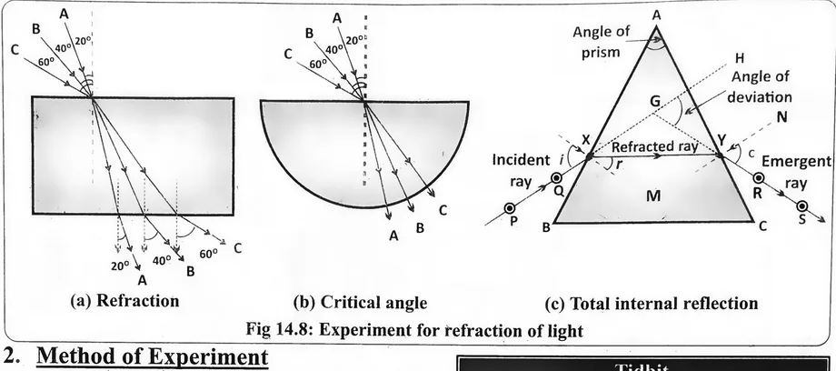
To understand how light bends (refracts) when it passes through different transparent materials, we can perform a simple experiment using blocks of different shapes right in our classroom or school laboratory (Fig.14.8).
1. Materials Needed
Laser light, protractor, paper sheet, pencil, ruler, and Perspex blocks (rectangular, semi-circular, and prism-shaped).
2. Method of Experiment
- Place the rectangular glass block on a sheet of paper and observe its result.
- Draw a straight line at one edge where the light will enter.
- Draw a normal (a straight perpendicular line) at the point where light will hit the block.
- Shine the laser light at an angle on the block along the drawn line.
Experiment to Study total internal reflection
To study how total internal reflection of light occurs using a semi-circular glass block (Fig.14.9).
Materials Needed
Light ray, protractor, paper, pencil, ruler, and a semi-circular Perspex (glass) block.
Figure (a) demonstrates the refraction, while Fig (b) and Fig. (c) illustrate the critical angle and total internal reflection respectively.
Optical Fibre
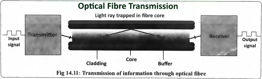
- Optical fibres use the principle of Total Internal Reflection (TIR) to transmit light efficiently over long distances.
- These fibres are widely used in the telecommunication industry due to their high speed and reliability.
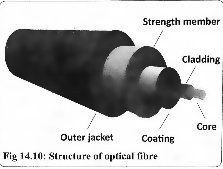
- An optical fibre consists of thin, hair-like strands made of glass or plastic (Fig. 14.10).
- It has two main parts: the core and the cladding.
- The core is the inner part that carries the light and is made of a material with a higher refractive index.
- Surrounding the core is the cladding, which has a lower refractive index and helps in total internal reflection. When light enters one end of the core, it hits the core-cladding boundary at an angle greater than the critical angle, causing it to reflect back into the core (Fig. 14.11).
- This repeated reflection allows light to travel long distances with minimal energy loss.
Advantages of Optical Fibres
Optical fibres are used in many areas of life, but their most common use is in modern telecommunications. Compared to traditional copper cables, optical fibres offer several key benefits:
1. High Bandwidth
- Optical fibres can carry a much larger amount of data than copper wires. Bandwidth means how much data can be sent over a network per second.
- In today's world, where we need fast internet, optical fibres are the best choice because they support high-speed data transfer.
2. Low Power Consumption
They use less power than copper cables. Also, because they last longer and are more durable, they reduce the cost of repairs and maintenance.
3. Faster Speed
They send data using light pulses, which travel extremely fast almost at the speed of light. This allows data to move quickly from one place to another, faster than electrical signals in copper wires.
4. Long Distance Transmission
Optical fibres can carry data across very long distances without losing signal quality. This makes them ideal for use in undersea cables and connections between continents.
5. Resistance to Electrical Interference
Since optical fibres use light instead of electricity, they are not affected by electrical noise or interference. This is a big advantage over copper wires, which often face signal problems due to electrical disturbances.
Lenses
Definition
"A lens is a transparent material with two surfaces, at least one of which is curved."
It bends (refracts) light in a way that forms an image of an object.
1. Uses
- Lenses come in different types and are widely used in optical devices such as cameras, eyeglasses, microscopes, telescopes, and projectors.
- They play an important role in correcting vision.
2. Types of Lenses
- Lenses are classified based on how they bend light rays.
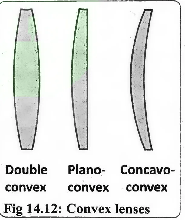
- A convex lens, also known as a converging lens, brings parallel light rays together at a point. It is thicker in the centre and thinner at the edges (Fig. 14.12).
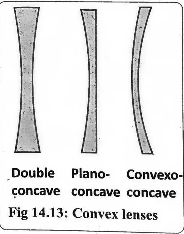
- On the other hand, a concave lens, also called a diverging lens, causes parallel light rays to spread out. This lens is thinner in the centre and thicker at the edges (Fig. 14.13).
3. Important Terms Related to Lenses
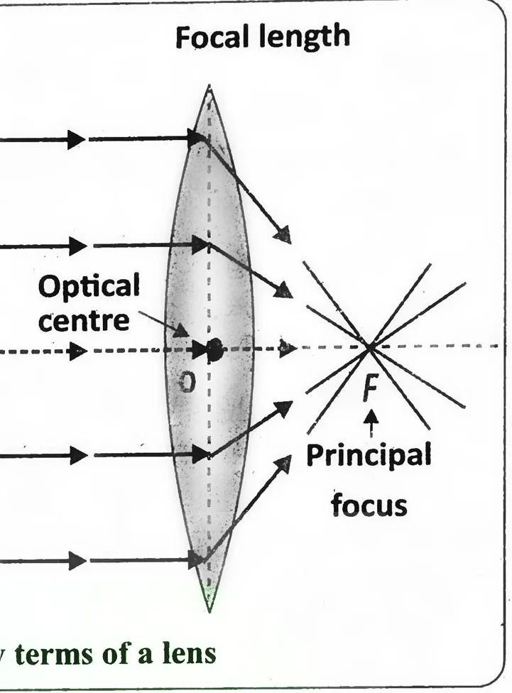
To understand how lenses form images, it is important to learn some basic terms as illustrated in Fig.(14.14).
a. Focal Length
The focal length (denoted as f) is the distance from the lens to its focal point, where light rays either meet (converge) or appear to spread out (diverge).
i. In converging lenses, focal length is positive and the rays meet at a point after passing through the lens.
ii. In diverging lenses, focal length is negative and rays seem to spread out from a virtual point on the same side of the lens as the light source.
b. Principal Axis
- This is a straight, imaginary line that passes through the centre of the lens.
- Light rays that travel along the principal axis do not bend or change direction when passing through the lens.
c. Principal Focus (Focal Point)
The principal focus is the point where light rays that are parallel to the principal axis come together (in converging lenses) or appear to come from (in diverging lenses).
(i) For a converging lens, the focus is on the opposite side of the incoming rays.
(ii) For a diverging lens, the focus is on the same side as the incoming rays and appears to be behind the lens.
d. Optical Centre
The optical centre is the geometrical middle point of the lens through which the principal axis passes. Light passing through this point does not bend. It is usually marked as O.
e. Centre of Curvature
Lenses are made from parts of a sphere. The centre of this imaginary sphere is called the center of curvature. It is generally located at twice the focal length from the lens.
Lens and Mirror Formula
The relationship between the focal length f, object distance p, and image distance q for both lenses and mirrors is expressed by the lens/mirror formula as:
1/f = 1/p + 1/q ................. (14.8)
This fundamental equation helps determine the position and nature of the image formed by a given optical system.
Key point Behaviour of converging lens to parallel beam of light
Behaviour of Converging Lens
Action of Lenses on Parallel Rays
When a set of parallel light rays pass through a lens, they refract and show specific patterns based on the lens type. Depending on how they interact with the rays, lenses are grouped into converging and diverging lenses.
1. Refraction and Convergence for Convex lens
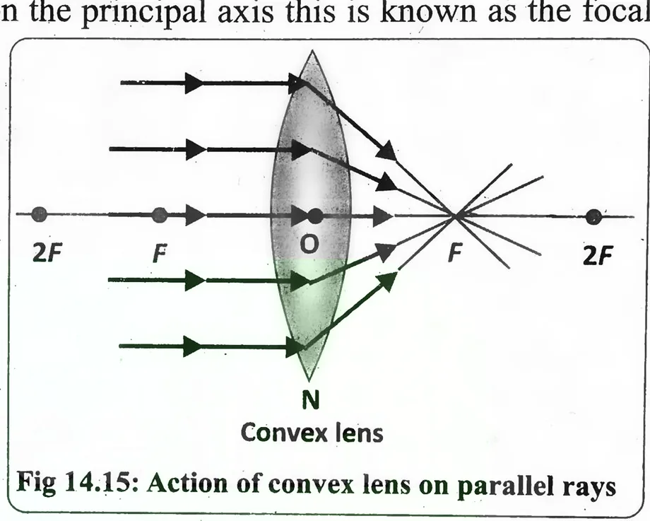
As the rays enter the lens, they bend towards the principal axis due to refraction. This bending takes place because of the lens's curved surfaces and its refractive index. After passing through the lens, all the rays meet at a common point on the principal axis this is known as the focal point.
2. Formation of Image
- The type of image formed depends on the object's distance from the lens.
- Generally, a converging lens forms a real and inverted image, but if the object is very close to the lens, the image can be virtual and upright. The ray behaviour for a converging lens is shown in Fig. 14.15.
3. Refraction and Divergence of Concave Lens
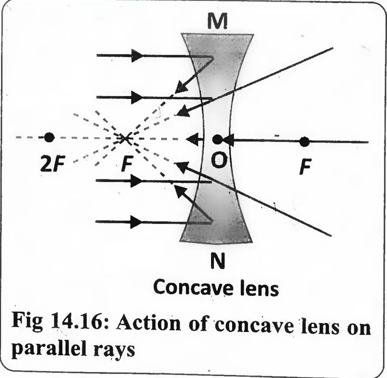
The rays are bent away from the principal axis. This bending gives the illusion that they originate from a point behind the lens, the virtual focus. This is a result of refraction through the curved surface of the lens.
4. Virtual Focal Point
In a diverging lens, the rays do not actually meet at a point. Instead, when extended backward, they appear to spread out from a common point on the same side of the lens. This is called a virtual focal point.
5. Formation of Image
When an object is placed far from a diverging lens (at infinity), the image formed is virtual, upright, and smaller than the actual object.
This behavior of diverging lenses is illustrated in Fig. (14.16).
Key points Power of a lens and its SI units
Power of a Lens
Definition The power of a lens measures its ability to bend light and is defined as the reciprocal of its focal length (f) in metres.
1. Mathematically
It is given by the formula:
P = 1 / f ..................... (14.9)
2. Unit
The SI unit of power is dioptre (D), where 1 dioptre (1 D) is the power of a lens with a focal length of 1 metre.
3. Explanation
- A convex lens has a positive focal length, so its power is positive.
- A concave lens has a negative focal length, so its power is negative.
- Lenses with higher power bend light more strongly, and this concept is important in eyeglasses, microscopes, and optical instruments.
Key points Rays for formation of images in convex lenses, Real and virtual images
Image Formation by Thin Lenses
Unlike mirrors, which form images through reflection, lenses create images through refraction. This process can be understood using ray diagrams.
1. Rules for Image Formation
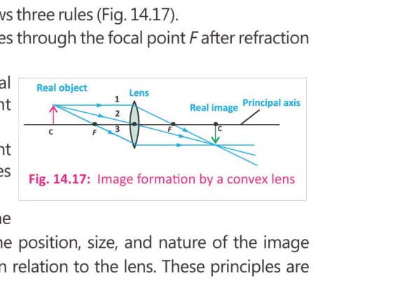
For a convex lens, image formation follows three rules (Fig. 14.17).
a. A ray parallel to the principal axis passes through the focal point F after refraction from the lens (ray-1).
b. A ray passing through the optical centre of the lens continues straight without bending (ray-2).
c. A ray passing through the focal point after refraction from the lens, becomes parallel to the principal axis (ray-3).
By tracing these rays, we can determine where and how an image is formed. The position, size, and nature of the image depend on where the object is placed in relation to the lens. These principles are important in devices like cameras, magnifying glasses, microscopes, and eyeglasses. The image formation by a convex lens for different positions is described in Table 14.2.
2. Formation of Real Image by a Converging Lens
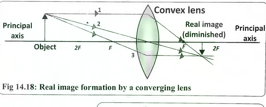
- A convex lens produces a real image when the object is placed beyond its principal focus (F). As illustrated in Fig. 14.18, the image appears on the opposite side of the lens from where the object is located.
- To determine the position and characteristics of an image formed by a convex lens, three rays are typically used as reference lines starting from a specific point on the object.
- The principal axis is the horizontal line passing through the optical centre of the lens.
- The resulting image in this setup is real, inverted, and smaller than the actual object as shown in Fig. 14.18.
3. Formation of a virtual image by a converging lens
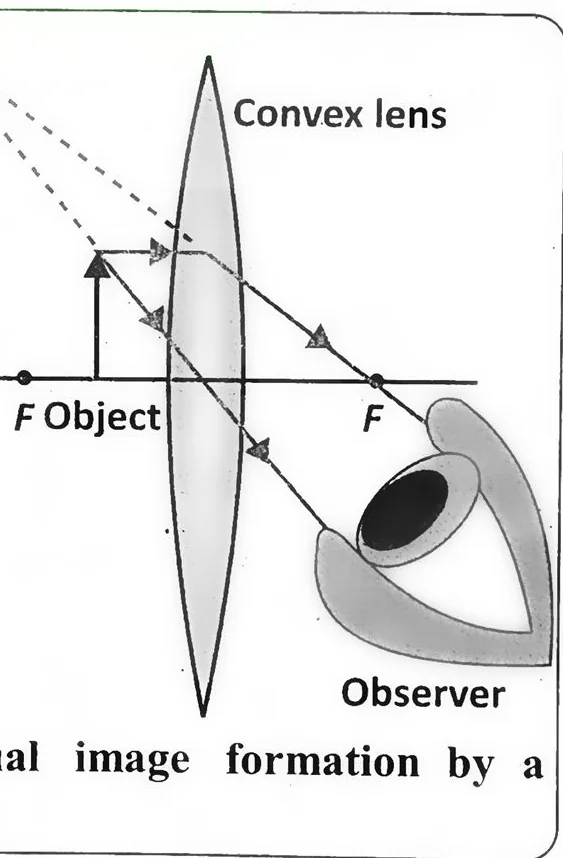
- For a convex lens to produce a magnified virtual image, the object should be placed between the lens and its principal focus, as illustrated in Fig. 14.19. In this arrangement, the image appears on the same side of the lens as the object.
- It is upright, larger in size, and cannot be projected onto a screen, as it is virtual.
- Such an image is visible only when viewed through the lens.
- This principle is used in magnifying glasses.
Difference between real and virtual images
Real Image
- Can be displayed or captured on a screen.
- Always appears upside down (inverted).
- Created when light rays actually meet after reflecting or refracting.
- Result of actual light rays intersecting.
- Can be displayed on a screen (like a wall or sensory).
- Example is the image on our TV screen.
Virtual Image
- Cannot be projected or caught on a screen.
- Always appears upright (erect).
- Created when light rays only seem to meet, they do not actually converge.
- Formed by the imaginary extension of diverging light rays.
- Example is our reflection in mirror.
Key points Linear magnification and its SI units
Linear Magnification
Definition "Linear magnification is the ratio of the height (or length) of the image to the height (or length) of the object." It indicates how much larger or smaller the image is compared to the object.
1. Mathematically
Linear Magnification = Image Height / Object Height
Or M = h₁ / h₀ ..................... (14.10)
Steps to Calculate Linear Magnification:
a. Measure the height of the object h₀
b. Measure the height of the image h₁
c. Use the formula m = h₁ / h₀
2. Unit
Linear magnification has no units.
Key point Applications of lenses in optical devices
Optical devices
Now we discuss applications of lenses in some optical devices such as camera, slide projector and photograph enlarger.
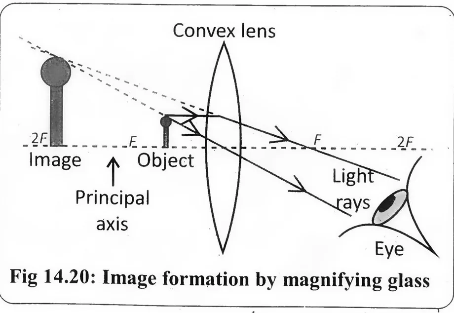
1. The Magnifying Glass
- A magnifying glass is a convex (converging) lens used to make objects appear larger.
- When an object is placed closer to the lens than its focal length (p < f), the refracted light rays do not meet but appear to come from a point behind the lens.
- This creates a virtual, upright, and magnified image, which cannot be projected on a screen (Fig.14.20).
- This simple use of a convex lens is also known as a simple microscope.
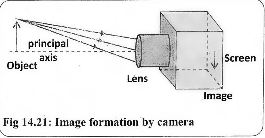
2. Camera
- A camera consists of a light-proof box with a convex lens at the front and a light sensitive film or sensor at the back.
- The lens focuses light onto the film to capture an image.
- In a simple camera, the lens-film distance is fixed and equal to the focal length of the lens.
- The object is placed beyond 2F, forming a real, inverted, and smaller (diminished) image on the film (Fig.14.21).
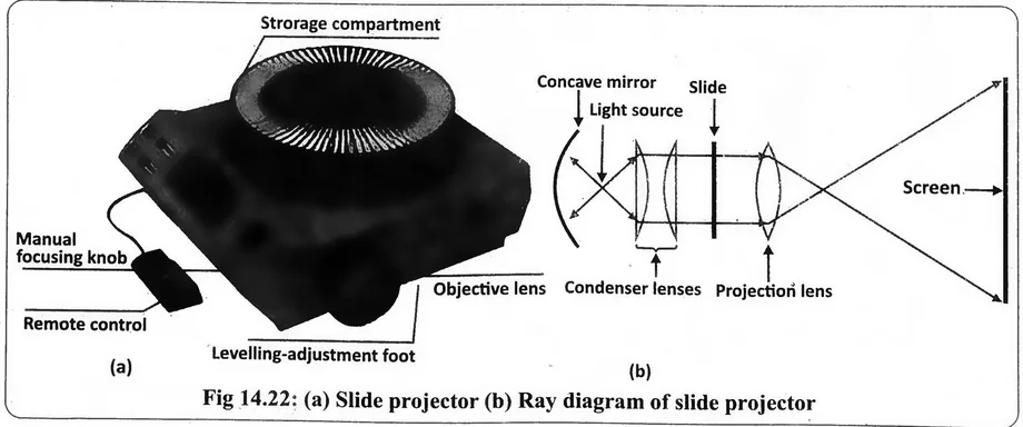
3. Slide Projector
- A slide projector works by projecting an enlarged image of a slide or film onto a screen Fig.(14.22-a).
- It consists of: A light source at the centre of a concave mirror, which reflects light as parallel rays.
- A condenser lens system (two plane convex lenses) that evenly distributes light across the slide.
- A projection lens (convex lens) that creates a real, large, and inverted image on the screen.
- To ensure the image appears correctly, the slide must be placed upside down because the projection lens inverts the image.
- The slide is positioned between F and 2F to form a real, magnified, and inverted image on the screen Fig.(14.22-b).
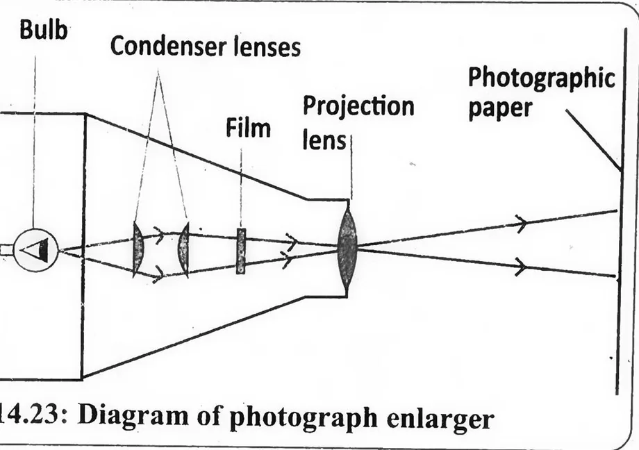
4. Photograph Enlarger
- A photograph enlarger works similarly to a slide projector but is used to enlarge photographs or negatives onto photographic paper (Fig. 14.23).
- The negative (object) is placed between F and 2F, forming a real, inverted, and enlarged image on the paper.
- The convex lens ensures that the final image is magnified, allowing small negatives to be printed as large photographs.
- These optical devices use convex lenses to manipulate light, forming images that are magnified, reduced, or projected for various practical applications.
Key points Image formation in a normal eye, Defects and remedies of image formation in a normal eye
Image Formation in a Normal Eye
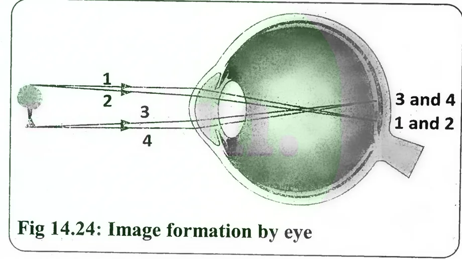
- In a healthy eye, light rays from an object pass through the cornea and lens, and are focused directly onto the retina, forming a sharp and clear image.
- As shown in Fig. 14.24, rays from the top and bottom of the object converge at specific points on the retina, allowing us to see a clear image.
- This process is similar to how a convex lens forms a real image.
1. Short-Sightedness (Myopia) and Its Correction
The closest distance from the eye where we can see things clearly is called near point. For a normal person, it is about 25 cm.
a. Short-sightedness is a condition where a person can clearly see nearby objects but struggles to see distant ones
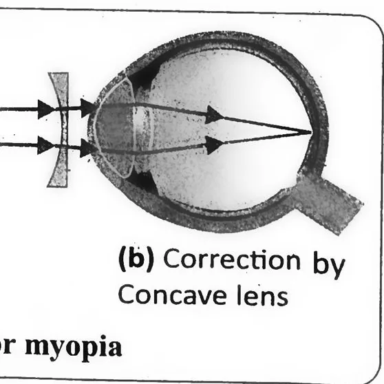
- This occurs when the eye lens bends light rays too strongly, causing the image to form in front of the retina instead of on it (Fig.(14.25-a). As a result, distant objects look blurry.
- To correct this, concave lenses are used in glasses or contact lenses.
- A concave lens spreads out the light rays before they enter the eye, helping the eye's natural lens to focus them correctly on the retina (Fig.(14.25-b).
b. Causes of Short-Sightedness (Myopia)
There are two main causes of short-sightedness:
(i) Lens too strong: The eye lens becomes too curved, focusing light in front of the retina.
(ii) Eyeball too large: The distance between the cornea and retina increases, so the focused image falls short of the retina.
2. Long-Sightedness (Hypermetropia) and Its Correction
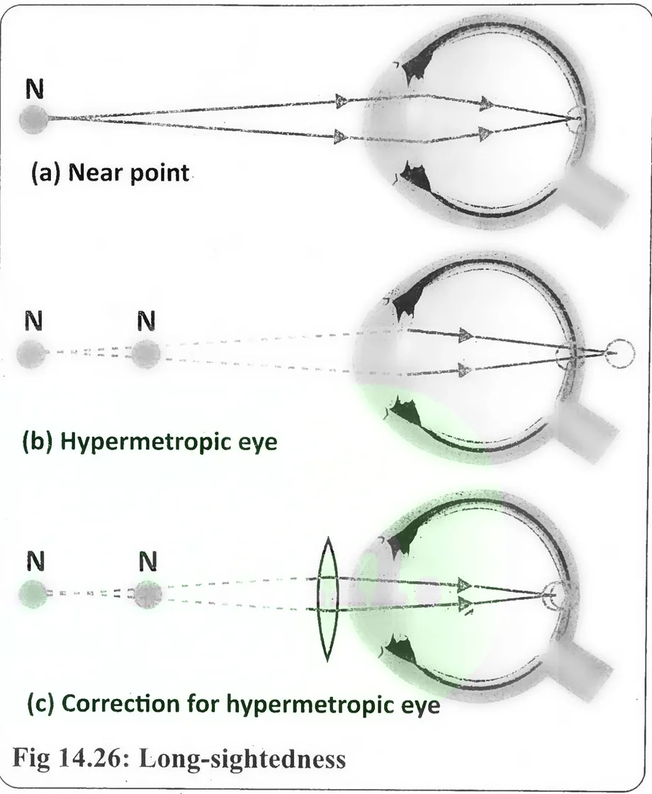
In a normal eye, light rays from nearby objects focus directly on the retina, creating a clear image (Fig. 14.26-a). However, in long-sightedness a person can see distant objects clearly, but nearby objects appear blurry. This happens when the eye lens is too weak or the eyeball is too small, so the light rays from near objects are not bent enough. As a result, the rays focus behind the retina instead of on it (Fig. 14.26-b)
- To correct this, convex lenses are used in glasses or contact lenses.
- A convex lens bends the light rays more before they enter the eye, helping them focus directly on the retina (Fig.(14.26-c).
Causes of Long-Sightedness
There are two main causes:
a. Lens too weak: The retina is too close to the lens.
b. Eyeball too small: The retina is too close to the lens.
In both cases, the image is formed behind the retina, making close-up vision blurry.
Key points Gravitational and acoustic lenses and uses of acoustic lenses
Gravitational Lens and Acoustic Lens
1. Gravitational Lensing
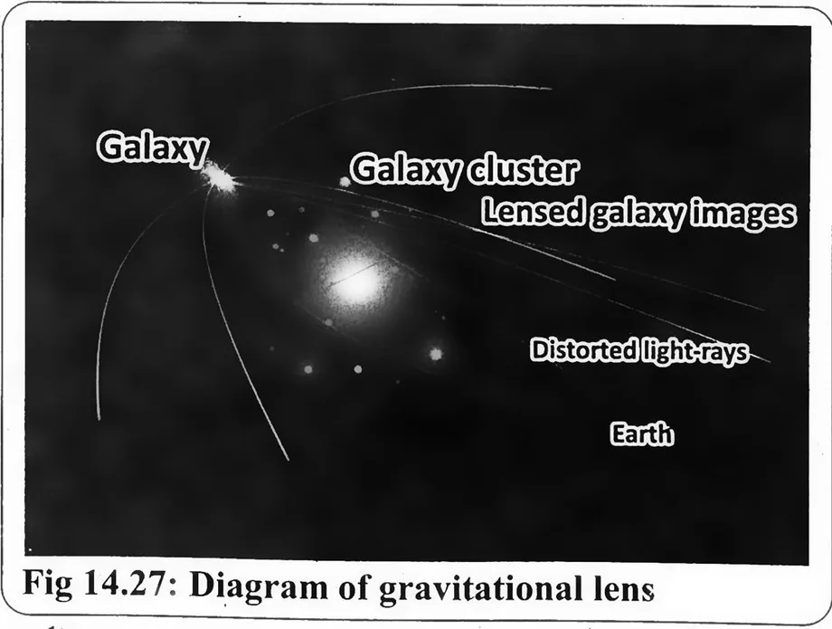
- Gravitational lensing occurs when the strong gravitational field of a massive object, like a black hole or galaxy, bends the path of light travelling near it. Just like an optical lens bends and focuses light, a massive celestial body acts as a "gravitational lens", altering the path of light from a distant object such as a star or galaxy.
- This effect can cause the distant object to appear magnified, distorted, or even duplicated, creating multiple images (Fig. 14.27).
- Gravitational lensing is a valuable tool in astronomy. It helps scientists study distant galaxies, dark matter, and the structure of the universe, providing insights into objects that are otherwise too far to observe directly.
2. Acoustic Lenses
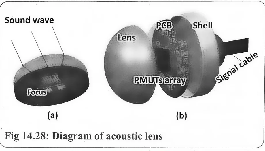
- Acoustic lenses are special devices designed to focus or spread sound waves, similar to how optical lenses control light.
- These lenses are made from materials with different acoustic properties and are shaped to redirect and focus sound waves.
- They can concentrate sound into a narrow beam or spread it over a wider area, improving sound clarity and control (Fig. 14.28).
- These lenses can focus sound to a specific point (like a microphone or sensor), or diverge sound to spread it over a wider area.
Acoustic lenses are widely used in:
a. Medical imaging (e.g., ultrasound) to improve scanning accuracy.
b. SONAR systems to detect underwater objects.
c. Noise control to focus or reduce sound in specific areas.
Both gravitational and acoustic lenses demonstrate how the principles of wave manipulation apply to both light and sound, playing an important role in astronomy, medicine, and technology.
Key point Dispersion of light by prism
Dispersion of Light by Prism
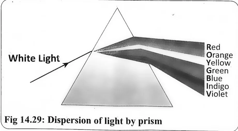
Definition "The splitting of white light into its seven constituent colours when passing through a prism is called dispersion of light."
1. Explanation
- A prism is an optical element typically made of glass with triangular and rectangular sides. It bends light passing through it due to refraction. Since visible light consists of a range of wavelengths, and refraction depends on different wavelengths bend at different angles, causing dispersion.
- When white light enters a prism, it slows down and bends toward the normal.
- Each colour has a unique wavelength, and as light travels through the prism, each wavelength refracts at a different angle.
- Shorter wavelengths (violet, blue) bend more than longer wavelengths (red, orange). As a result, the light exiting the prism separates into seven distinct colours red, orange, yellow, green, blue, indigo, and violet forming the visible light spectrum (Fig. 14.29).
- Beyond the visible spectrum, prisms can also disperse infrared (IR) and ultraviolet (UV) light, though these wavelengths are invisible to the human eye.
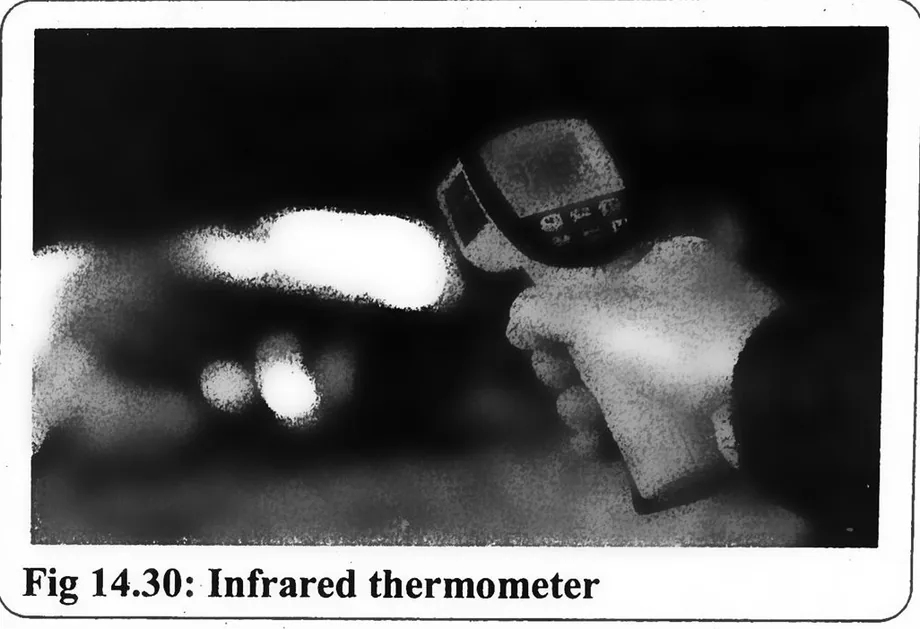
- Special detection methods, such as infrared thermometers with sensors, are used to measure these wavelengths.
2. Infrared Thermometers
- These devices detect IR radiation emitted by objects, which correlates with their temperature.
- When dispersed light from a prism reaches an IR thermometer, it can measure both visible and infrared light.
- By analyzing the intensity of IR radiation, the thermometer determines the temperature of the emitting object.
- This technology allows for non-contact temperature measurement, such as checking human body temperature (Fig.14.30).
More figures from this unit