 StudentAid
Unit 15: Electromagnetic Induction — Long Questions
12th Class Physics · Unit 15: Electromagnetic Induction
As soon as Oersted discovered that electric currents produce magnetic fields, many scientists began to look for the reverse effect, that is, to cause an electric current by means of a magnetic field. In 1831 Michael Faraday in England and at the same time Joseph Henry in USA observed that an emf is set up in a conductor when it moves across a magnetic field. If the moving conductor was connected to a sensitive galvanometer, it would show an electric current flowing through the circuit as long as the conductor is kept moving in the magnetic field. The emf produced in the conductor is called induced emf, and the current generated is called the induced current. This phenomenon is known as electromagnetic induction.
INDUCED emf AND INDUCED CURRENT
There are many ways to produce induced emf. Figure illustrates one of them. Consider a straight piece of wire of length l placed in the magnetic field of a permanent magnet. The wire is connected to a sensitive galvanometer. This forms a closed path or loop without any battery. In the beginning when the loop is at rest in the magnetic field, no current is shown by the galvanometer. If we move the loop from left to right, the length l of the wire is dragged across the magnetic field and a current flows through the loop. On reversing the direction of motion of the loop, current also reverses its direction. This is indicated by the deflection of the galvanometer in opposite direction.
The induced current depends upon the speed with which conductor moves and upon the resistance of the loop. If we change the resistance of the loop by inserting different resistors in the loop and move it in the magnetic field with the same speed every time we find that the product of induced current I and the resistance R of the loop remains constant, i.e.,
I x R = Constant
This constant is the induced emf. The induced emf leads to an induced current when the circuit is closed. The current can be increased by
(i) Using a stronger magnetic field.
(ii) Moving the loop faster.
(iii) Replacing the loop by a coil of many turns.
If we perform the above experiment in the other way, i.e., instead of moving the loop across the magnetic field, we hold the loop stationary and move the magnet, then it can be easily observed that the results are the same. Thus it can be concluded that it is the relative motion of the loop and the magnet that causes the induced emf.
In fact, this relative motion changes the magnetic flux through the loop, therefore, we can say that an induced emf is produced in a loop if the magnetic flux through it changes. The greater the rate of change of flux, the larger is the induced emf.
There are some other methods described below in which an emf is induced in a loop by producing a change of magnetic flux through it.
(1) Figure (a) shows a bar magnet and a coil of wire to which a galvanometer is connected. When there is no relative motion between the magnet and the coil, the galvanometer indicates no current in the circuit. As soon as the bar magnet is moved towards the coil, a current appears in it figure (b). As the magnet is moved, the magnetic flux through the coil changes, and this changing flux produces the induced current in the coil. When the magnet moves away from the coil, a current is again induced but now in opposite direction. The current would also be induced if the magnets were held stationary and the coil is moved.
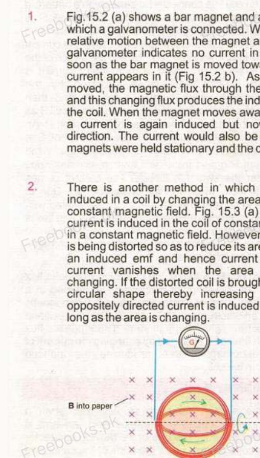
(2) There is another method in which the current is induced in a coil by changing the area of the coil in a constant magnetic field. Fig. 15.3a shows that no current is induced in the coil of constant area that is placed in a constant magnetic field. However, when the coil is being distorted so as to reduce its area, (Fig. 15.3b) and induced emf and hence current appears. The current vanishes when the area is no longer changing. If the distorted coil is brought to its original circular shape thereby increasing the area, an oppositely directed current is induced which lasts as long as the area is changing.
(3) An induced current can also be generated when a coil of constant area is rotated in a constant magnetic field. Here, also, the magnetic flux through the coil changes. This is the basic principle used in electric generators.
(4) A very interesting method to induce current in a coil involves by producing a change of magnetic flux in a nearby coil. Fig. 15.5 shows two coils placed side by side. The coil P is connected in series with a battery, a rheostat and a switch, while the other coil S is connected to a galvanometer only. Since there is no battery in the coil S, one might expect that the current through it will always be zero. Now, if the switch of the coil P is suddenly closed, a momentary current is induced in coil S. This is indicated by the galvanometer, which suddenly deflects and then returns to zero. When the current charges from zero in coil P, the magnetic flux due to this current also changes in coil P. This changing flux is also linked with the coil S that causes the induced current in it. Current in coil P can also be changed with the help of rheostat.
(5) It is also possible to link the changing magnetic flux with a coil by using an electromagnet instead of a permanent magnet. The coil is placed in the magnetic field of an electromagnet. Both the coil and the electromagnet are stationary. The magnetic flux through the coil is changed by changing the current of the electromagnet, thus producing the induced current in the coil.
MOTION emf
The emf induced by the motion of a conductor across a magnetic field is called motional emf. Consider a conducting rod of length L placed on two parallel metal rails separated by a distance L. A galvanometer is connected between the ends c and d of the rails. This forms a complete conducting loop abcda. A uniform magnetic field B is applied directed into the page. Initially when the rod is stationary, galvanometer indicates no current in the loop. If the rod is pulled to the right with constant velocity v, the galvanometer indicates a current flowing through the loop. Obviously, the current is induced due to the motion of the conducting rod across the magnetic field. The moving rod is acting as a source of emf ε = Vb – Va = ΔV.
When the rod moves, a charge q within the rod also moves with the same velocity v in the magnetic field B and experiences a force given by
→F = q V × B
The magnitude of the force is
F = qvB sin θ
Since angle θ between v and B is 90°, so
F = qvB
Applying the right hand rule, we see that F is directed from a to b in the rod. As a result the charge migrates to the top end of the conductor. As more and more of the charges migrate, concentration of the charge is produced at the top b and a deficiency of charges at the bottom end a. This redistribution of charge sets up an electrostatic field E directed from b to a. The electrostatic force on the charge is Fo = qE directed from b to a. The system quickly reaches an equilibrium state in which these two forces on the charge are balanced. If Eo is the electric intensity in this state then
qEo = vB
Eo = vB . . . . (i)
The motional emf ε will be equal to the potential difference ΔV = Vb – Va between the two ends of the moving conductor in this equilibrium state. The gradient of potential will be given by ΔV/L. As the electric intensity is given by the negative of the gradient therefore,
Eo = -ΔV/L . . . . (ii)
Using eq. (i)
or ΔV = -LEo
= -(LvB)
The motional emf
ε = ΔV = -LvB
This is the magnitude of motional emf. However, if the angle between v and B is θ, then
ε = -VBL sin θ
Due to induced emf positive charges would flow along the path abcda, therefore the induced current is anticlockwise in the diagram. As the current flows the quantity of the charge at the top decreases so the electric intensity decreases but the magnetic force remains the same. Hence the equilibrium is disturbed in favour of magnetic force. Thus as the charges reach the end a of the conductor due to current flow, they are carried to the top b of the conductor by the unbalanced magnetic force and the current continues to flow.
FARADAY'S LAW AND INDUCED emf
This law states that "the average emf induced in a conducting coil of N loops is equal to the negative of the rate at which the magnetic flux through the coil is changing with time".
Explanation
Consider a conducting rod L moves from position 1 to position 2 in a small interval of time. The distance travelled by the rod in time Δt is
Δx = x2 – x1
Since the rod is moving with constant velocity v, therefore
v = Δx/Δt
As the motional emf is
ε = -VBL
Putting value of 'v'
ε = -Δx/Δt × BL
ε = -ΔxBL/Δt . . . . (i)
As the rod moves through the distance Δx, the increase in the area of loop is given by
ΔA = Δx · L
Thus increase in the flux through the loop is given by
ΔΦ = BΔA
or ΔΦ = Δx · L · B
Putting this in eq. (i)
ε = -ΔΦ/Δt
If there is a coil of N loops instead of a single loop, then the induced emf will become N times, i.e.,
ε = -N ΔΦ/Δt
The negative sign indicates that the direction of the induced emf is such that it opposes the change in flux.
Note Although the above expression is derived on the basis of motional emf, but it is true in general. This conclusion was first arrived at by Faraday, so this is known as Faraday's law of electromagnetic induction.
LENZ'S LAW AND DIRECTION OF INDUCED emf
The law states that, "the direction of the induced current is always so as to oppose the change which causes current".
Explanation
According to Faraday's law of electromagnetic induction
ε = -N ΔΦ/Δt
The negative sign indicates the direction of the induced emf. To determine the direction we use a method based on the discovery made by the Russian Physicist Heinrich Lenz in 1834. He found that the polarity of an induced emf always leads to an induced current that opposes, through the magnetic field of the induced current, the change inducing the emf.
The Lenz's law refers to induced currents and not to induced emf, which means that we can apply it directly to closed conducting loops or coils. However, if the loop is not closed we can imagine as if it were closed, and then from the direction of induced current, we can find the direction of the induced emf.
Let us apply the Lenz's law to the coil in which current is induced by the movement of a bar magnet. We know that a current carrying coil produces a magnetic field similar to that of a bar magnet. One face of the coil acts as the north pole while the other one as the south pole. If the coil is to oppose the motion of the bar magnet, the face of the coil towards the magnet must become a north pole. The two north poles will then repel each other. The right hand rule applied to the coil suggests that the induced current must be anticlockwise as seen from the side of the bar magnet.
According to Lenz's law the "push" of the magnet is the "change" that produces the induced current, and the current acts to oppose the push. On the other hand if we pull the magnet away from the coil the induced current will oppose the "pull" by creating a south pole on the face of coil towards the bar magnet.
The Lenz's law is also a statement of law of conservation of energy that can be conveniently applied to the circuits involving induced currents. To understand this, consider once again the experiment in figure. When the rod moves towards right, emf is induced in it and an induced current flows through the loop in the anti-clockwise direction. Since the current carrying rod is moving in the magnetic field, it experiences a magnetic force Fm having the magnitude
Fm = ILB sin 90°
By right hand rule the direction of Fm is opposite to that of v, so it tends to stop the rod. An external dragging force equal to F in magnitude must be opposite in direction must be applied to keep the rod moving at constant velocity. This dragging force provides the energy for the induced current to flow. This energy is the source of energy for induced current flow, thus electromagnetic induction is exactly according to law of conservation of energy.
The Lenz's law forbids the induced current directed clockwise in this case, because the force Fm would be, then, in the direction of v that would accelerate the rod towards right as shown. This in turn would induce a stronger current, the magnetic field due to it also increases and the magnetic force increases further. Thus the motion of the wire is more accelerated and so on. Commencing with a minute quantity of energy, we obtain an every increasing kinetic energy of motion apparently from nowhere. Thus the process becomes self-perpetuating which is against the law of conservation of energy.
MUTUAL INDUCTION
The phenomenon in which a changing current in one coil induces an emf in another coil is called the mutual induction.
Explanation
Consider two coils placed closed to each other as shown in figure. One coil connected with a battery through a switch and a rheostat is called the primary and the other one connected with galvanometer is called the secondary. If the current in the primary is changed by varying the resistance of the rheostat, the magnetic flux in surrounding region changes. Since the secondary coil is in the magnetic field of the primary, the changing flux also links with the secondary. This causes an induced emf in the secondary.
Let the flux passing through each loop of secondary is equal to φs. Net flux passing through Ns loops = Ns φs, where Ns is the number of turns in the secondary coil.
As φ = BA
∴ φ ∝ B . . . . (i)
Also B ∝ IP . . . . (ii)
From (i) and (ii)
φ ∝ IP
∴ Ns φs ∝ IP
Ns φs / IP
where M = Ns φs / IP is the constant of proportionality called the mutual inductance of the two coils. It depends upon the number of turns of the coil, their area of cross-section, their closeness together and the nature of the core upon which the two coil are wound.
According to Faraday's law
εs = -Ns ΔΦ/Δt
εs = -A (Ns φs / Δt)
Putting the value of Ns φs = MIP
εs = - AMIP / Δt
∴ εs = - M ΔIP / Δt
Mutual Inductance
As M = εs / (ΔIP/Δt)
The ratio of average emf induced in the secondary to the time rate of change of current in primary is called the mutual inductance.
Unit of Mutual Inductance
The SI unit of mutual inductance is VA-1 s which is called Henry (H).
Henry
One henry is the mutual inductance of the pair of the coils in which a rate of change of current of one ampere per second in the primary caused an induced emf of one volt in the secondary.
SELF INDUCTION
The phenomenon in which a changing current induces an emf in itself is called self induction.
Explanation
Consider a circuit as shown in figure. A coil is connected in series with a battery and a rheostat. Magnetic flux produced through the coil due to current in it. If the current is changed by varying the rheostat quickly magnetic flux through the coil changes that causes an induced emf in the coil. Such an emf is called as self induced emf.
Let flux through one loop of the coil is equal to φ.
Total flux through the coil of N turns = Nφ
As φ = BA ...... (A)
φ ∝ B ...... (i)
B ∝ I ...... (ii)
From (i) and (ii)
φ ∝ I
∴ Nφ ∝ I
Nφ = LI
L = Nφ/I
Where L is the constant of proportionality called the self inductance of the coil.
It depends upon the number of turns of the coil, its area of cross-section and the core material. By winding the coil around a ferromagnetic (iron) core, the magnetic flux and hence the inductance can be increased relative to that for an air core.
By Faraday's law
εL = −N Δφ/Δt
εL = −Δ(Nφ)/Δt
Putting the value of Nφ = LI
∴ εL = −Δ(LI)/Δt ...... (iii)
εL = −L ΔI/Δt
εL ∝ ΔI/Δt
This shows that self induced emf in a coil is directly proportional to the time rate of change of current in the coil.
Self Inductance
As L = εL/(ΔI/Δt)
The ratio of average emf to the rate of change of current in the coil is called self inductance.
Unit of Self Inductance
SI unit of self induction is also Henry (H).
The negative sign in eq. (iii) indicates that the self induced emf must oppose the change that produced it. That is why self induced emf is sometimes called back emf. This is exactly in accordance with Lenz's law. If current is increased the induced emf will be opposite to that of battery and if current is decreased the induced emf will aid the battery. Because of their self inductance, coils of wire are known as inductors. In A.C. inductors behave like resistors.
ENERGY STORED IN AN INDUCTOR
As energy can be stored in the electric field between the plates of the capacitors. Similarly energy can be stored in the magnetic field of an inductor. Inductor is a device which can store energy due to magnetic field.
Consider a coil connected to a battery and a switch in series as shown in figure. When the switch is turned on voltage V is applied across the ends of the coil and current through it rises from zero to its maximum value I. Due to the change of current, an emf induced which is opposite to that of battery. Work is done by the battery to move charges against the induced emf.
From the definition of potential difference
V = W/Δq
W = VΔq
Work done by the battery in moving a small charge Δq is
W = εL Δq ...... (i) (∴ V = εL)
where εL is the magnitude (self induced emf) of induced emf given by
εL = L ΔI/Δt
Putting this value of εL in eq. (i)
∴ W = L ΔI/Δt Δq
W = L Δq/Δt ΔI
Here
Average current = Δq/Δt = (0 + I)/2
Δq/Δt = 1/2 I
Change in current = ΔI = I − 0
ΔI = I
∴ W = L(1/2 I)(I)
W = 1/2 LI2
This work is stored as potential energy in the inductor. Hence the energy stored in an inductor is
Um = 1/2 LI2 ...... (ii)
Energy Stored in Terms of Magnetic Field
As for solenoid
B = μ₀nI
As φ = BA
Putting value of B
∴ φ = μ₀nAI
As Nφ = LI
L = Nφ/I
Putting value of φ
∴ L = N/I (μ₀nAI)
L = Nμ₀nA
As n = N/l
N = nl
L = n/l μ₀nA
L = μ₀n2 (Al)
Putting this value in (ii)
Um = 1/2 (μ₀n2 Al) I2 ...... (iii)
As B = μ₀nI
I = B/(μ₀n)
Putting value of I in eq. (iii)
Um = 1/2 μ₀n2 Al (B2/(μ₀n)2)
Um = 1/2 B2/μ₀ (Al)
Energy Density
Energy density can be defined as the energy stored per unit volume inside the solenoid.
Ed = E/Volume = Um/Volume
= [1/2 B2/μ₀ (Al)]/Al
Ed = 1/2 B2/μ₀
ALTERNATING CURRENT GENERATOR
A current generator is a device that converts mechanical energy into electrical energy.
Principle
It is based on Faraday's law of electromagnetic induction i.e., when a coil is rotated in a magnetic field by some mechanical means, magnetic flux through the coil changes and hence an emf is induced in the coil.
Construction
A rectangular loop of wire of area A is placed in a uniform magnetic field B, as shown in figure. The loop is rotated about z-axis through its centre at constant angular velocity ω. One end of the loop is attached to a metal ring R and the other end to the ring R'. These rings, called the slip rings, are concentric with the axis of the loop and rotate with it. Rings RR' slide against stationary carbon brushes to which external circuit is connected.
Working
Now we calculate the induced emf in the loop, consider its position while it is rotating anticlockwise (top view). The vertical side ab of the loop is moving with velocity v in the magnetic field B. If the angle between v and B is θ, the motional emf induced in this side has the magnitude.
εab = vBL sin θ
The direction of the induced current in the wire ab is the same as that of force F experienced by the +ve charges in the wire i.e., from top to bottom. The same amount of emf is induced in the side cd but the direction of the current is from bottom to the top.
The net contribution to emf by sides bc and da is zero because the force acting on the charges inside bc and da is not along the wire.
∴ εdc = vBL sin θ
∴ εcd = εda = 0
Since both the emf's in the sides ab and cd drives the current in the same direction around the loop, the total emf is
ε = εab + εcd
= vBL sin θ + vBL sin θ
ε = 2vBL sin θ
If the loop is replaced by a coil of N turns then
ε = 2NvBL sin θ ...... (i)
The linear speed v of the vertical wire is related to the angular speed ω as
v = rω
where r is the distance of the vertical wires from the centre of the coil.
∴ eq. (i) becomes
ε = 2NrωBL sin θ
ε = NB(2rL) B sin θ
As 2rL = A = Area of coil
∴ ε = NBΑω sin θ
Since θ = ωt
∴ ε = NBΑω sin ωt ...... (ii)
This equation shows that this induced emf varies sinusoidally with time. It has the maximum value when sin ωt = 1
∴ εo = NBΑω
Therefore eq. (ii) becomes
ε = εo sin ωt ...... (iii)
If R is the resistance of the coil, then by Ohm's law the induced current in the coil will be
I = ε/R
Putting value of ε from eq. (iii)
∴ I = εo sin ωt/R ...... (iv)
Maximum induced current is
Io = εo/R (as max value of sin ωt = 1)
∴ I = Io
As angular speed ω of the coil is related to its frequency f as
T = 2π/ω
ω = 2π/T
ω = 2πf (1/T = f)
Therefore eq. (iii) and (v) becomes
ε = εo sin 2πft ...... (vi)
I = Io sin 2πft ...... (vii)
Explanation from Graph
When the angle between v and B is θ = 0, the plane of the loop is perpendicular to B, current is zero. As θ increases, current also increases and at θ = 90° = π/2 rad, the loop is parallel to B, current is maximum, directed along abcda. On further increase in θ current becomes zero as the loop is again perpendicular to B. For 180° < θ < 270° current increases but reverses its direction as is clear from the figure. Current is now directed along dcbad. At θ = 270° = 3π/2 rad, current is maximum in the reverse direction as the loop is parallel to B. At θ = 360° = 2π rad, one rotation is completed, the loop is perpendicular to B and the current decreases to zero. After one rotation the cycle repeats itself. The current alternates in direction once in one cycle. Therefore, such a current is called the alternating current. It reverses its direction f times per second.
Note In actual practice a number of coils are wound around an iron cylinder which is rotated in the magnetic field. This assembly is called an armature. The magnetic field is usually provided by an electromagnet. Armature is rotated by a fuel a engine or a turbine run by a waterfall. In some commercial generation field magnet is rotated around a stationary armature.
D.C. GENERATOR
Alternating current generators are not suitable for many applications to run a D.C. motor. In 1834 William Sturgeon invented a simple device called a commutator that prevents the direction of current from changing. Therefore a D.C. generator is similar to the A.C. generator in construction with the difference that "slip rings" are replaced by "split rings" or "split rings" are two halves of a ring that act as a commutator figure shows the "split rings" A and A' attached to the two ends of the coil that rotates in the magnetic field. When the current in the coil is zero and is about to change direction, the split rings also change the contacts with the carbon brushes BB'. In this way the
output from BB' remains in the same direction, although the current is not constant in magnitude. The curve of the current is shown in figure.
It is similar to a sine curve with the lower half inverted. The fluctuations of the output can be significantly reduced by using many coils rather than a single one. Multiple coils are wound around a cylindrical core to form the armature. Each coil is connected to a separate commutator and the output of every coil is tapped only as it reaches its peak emf. Thus the emf in the outer circuit is almost constant.
BACK MOTOR EFFECT IN GENERATORS
A generator is the source of electricity production. Practically, the generators are not so simple as described above. A large turbine is turned by high pressure steam or waterfall. The shaft of the turbine is attached to the coil which rotates in a magnetic field. It converts the mechanical energy of the driven turbine to electrical energy. The generator supplies current to the external circuit. The devices in the circuit that consume electrical energy are known as the "load". The greater the load the larger the current is supplied by the generator.
When the circuit is open, the generator does not supply electrical energy, and a very little force is needed to rotate the coil. As soon as the circuit is closed, a current is drawn through the coil. The magnetic field exerts force on the current carrying coil. Figure shows the forces acting on the coil. Force F₁ is acting on the left side of the coil whereas an equal but opposite force F₂ acts on the right side of the coil. The forces are such that they produce a counter torque that opposes the rotational motion of the coil. This effect is sometimes referred to as back motor effect in the generators. The larger the current drawn, the greater is the counter torque produced. That means more mechanical energy is required for the coil rotating with constant angular speed. This is in agreement with the law of conservation of energy. The energy consumed by the "load" must come from the "energy source" used to drive the turbine.
D.C. MOTOR
A motor is a device which converts electrical energy into mechanical energy. We already know that a wire carrying current placed in a magnetic field experiences a force. This is the basic principle of an electric motor. In construction a D.C motor is similar to a D.C generator, having a magnetic field, a commutator and an armature. In the generator, the armature is rotated in the magnetic field and current is the output. In the D.C., magnetic field and current is the output. In the D.C. motor, the brushes are connected to a D.C supply or battery. When current flows through the armature coil, the force on the conductors produces a torque, that rotates the armature. The amount of this torque depends upon the current, the strength of the magnetic field, the area of the coil and the number of turns of the coil.
If the current in the coil were all the time in the same direction, the torque on it would be reversed after each half revolution. But at this moment, commutator reverses the direction of current that keeps the torque always in the same sense. A little problem arises due to the use of commutator. That is, the torque vanishes each time the current changes its direction. This creates jerks in the smooth running of the armature. However the problem is overcome by using more than one coils wrapped around a soft-iron core. This results in producing a more steady torque.
The magnetic field in the motor, is provided by a permanent magnet or an electromagnet. The windings of the electromagnet are usually called the field coils. The field coils may be in series or in parallel to the armature coils.
BACK emf EFFECT IN MOTORS
A motor is just like a generator running in reverse. When the coil of the motor rotates across the magnetic field by the applied potential difference V, an emf ε is induced in it. The induced emf is in such a direction that opposes the emf running the motor. Due to this reason the induced emf is called back emf of the motor. The magnitude of the back emf increases with the speed of motor.
Since V and ε are opposite in polarity, the net emf in the circuit is V − ε. If R is the resistance of the coil and I the current drawn by the motor, then by Ohm's law
I = (V − ε)/R
When the motor is just started, back emf is almost zero and hence a large current passes through the coil. As the motor speeds up, the back emf increases and the current becomes smaller and smaller. However, the current is sufficient to provide torque on the coil to drive the load and to overcome losses due to friction. If the motor is overloaded, it slows down. Consequently, the back emf decreases and allows the motor to draw more current. If the motor is overloaded beyond its limits, the current could be so high that it may burn the motor out.
TRANSFORMER
"A transformer is an electrical device to change a given alternating emf into a larger or smaller emf".
Principle
It works on the principle of mutual induction between two coils.
Construction
The transformer consists of two coils of copper, electrically insulated from each other, wound on the same iron core. The coil to which A.C power supplied is called primary and that from which power delivered to the circuit is called secondary.
Working
As there is no electrical connection between the two coils but they are magnetically linked. Suppose that an alternating emf is applied to the primary. If at some instant Δt, the flux in the primary is changing at the rate of Δφ/Δt then there will be back emf induced in the primary which will oppose the applied voltage.
∴ Self induced emf = −Np Δφ/Δt
If the resistance of the coil is negligible then back emf is equal and opposite to the applied voltage Vp.
∴ Vp = − Back emf
Vp = −(−Np Δφ/Δt)
Vp = Np Δφ/Δt ...... (i)
where Np is the number of turns in the primary.
Let the flux through the primary also passes through the secondary i.e., the two coils are tightly coupled, the rate of change of flux in the secondary will also be Δφ/Δt and the magnitude of induced emf across the secondary is given by
Vs = Ns Δφ/Δt ...... (ii)
where Ns is the no. of turns in the secondary.
Divide eq. (i) by (ii)
Vs/Vp = (Ns Δφ/Δt)/(Np Δφ/Δt)
Vs/Vp = Ns/Np
This relation is true only when secondary coil is in an open circuit i.e., not joined to a load.
Step up Transformer
If Ns > Np, then Vs > Vp such a transformer in which voltage across secondary is greater than the primary voltage is called a step-up transformer.
Step Down Transformer
If Ns < Np, then Vs < Vp, such a transformer in which voltage across the secondary is less than the primary voltage is called step down transformer.
Electrical Power in Transformer
The electrical power in a transformer is transformed from its primary to the secondary coil by means of changing flux.
For an ideal transformer
Pinput = Poutput
Vp Ip = Vs Is
Vp/Vs = Is/Ip
Ip is the current in the primary and
Is is the current in the secondary.
The currents are thus inversely proportional to the respective voltages.
Applications
In a step up transformer when the voltage across the secondary is raised, the value of current is reduced. This is the principle behind its use in the electric supply network where transformer increases the voltage and reduces the current so that it can be transmitted over long distance without much power loss. When current I passes through resistance R, the power loss due to heating effect is I²R. In order to minimize the loss during transmission, it is not possible to reduce R because it requires the use of thick copper wires which become highly uneconomical. The purpose is well served by reducing I. At the generating over station the voltage is stepped up to several thousand of volts and power is transmitted at low current to long distances without much loss.
Step down transformer decreases the voltage to a safe value at the end of line where the consumer of electric power is located. Inside a house transformer may be used to step down the voltage from 250 V to 9 volts for ringing bell or operating a transistor radio. The transformers with several secondary are used in television and radio receives where several different voltages are required.
POWER LOSSES IN TRANSFORMER
The output of a transformer is always less than input due to power losses. There are two main causes of the power loss.
(i) Eddy Current (ii) Hysteresis Loss
In order to enhance the magnetic flux, the primary and secondary coils of the transformer are wound on soft iron core. The flux generated by the coils also passes through the core. As magnetic flux changes through a solid conductor, induced currents are set up in closed paths in the body of the conductor. These induced currents are set up in a direction perpendicular to the flux and are known as eddy currents. It results in power dissipation and heating of the core material. In order to minimize the power loss due to flow of these currents, the core is laminated with insulation in between the layers of laminations which stops the flow of eddy currents (Figure).
Hysterises loss is the energy expended to magnetize and demagnetize the core material in each cycle of the A.C.
Efficiency of Transformer
Due to these power losses, a transformer is far from being an ideal. Its output power is always less than its input power. The efficiency of a transformer is defined as
E = (Output power)/(Input power) × 100%
In order to improve the efficiency, care should be exercised, to minimize all the power losses. For example core should be assembled from the laminated sheets of a material whose hysteresis loop area is very small. The insulation between lamination sheets should be perfect so as to stop the flow of eddy currents. The resistance of the primary and secondary coils should be kept to a minimum. As power transfer from primary to secondary takes place through flux linkages, so the primary and secondary coils should be wound in such a way that flux coupling between them is maximum.