StudentAid
Unit 5: Solids and Fluid Dynamics — Long Questions
11th Class Physics · Unit 5: Solids and Fluid Dynamics
Classification of Solids
Solids consist of the following types
1. Crystalline Solids
2. Amorphous or Glassy solids
3. Polymeric Solids
Brief explanation of these solids is as follows:
1. Crystalline Solids:
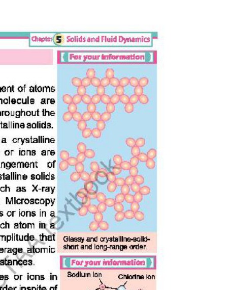
Crystalline solids are those solids in which their atoms and molecules are arranged in particular fashion.
Examples: quartz, calcite, sugar, mica and diamond etc.
Properties of crystalline solids:
(i) The arrangement of atoms and molecules is represented in the solid in 3-dimensions. e.g., Metals like copper (Cu), Iron (Fe), Zinc (Zn) and ionic compounds like sodium chloride (NaCl) and ceramics like zirconia are crystalline solids. The crystal structure is usually studied by diffraction of X-rays from crystals and transmission electron microscopy (TEM).
(ii) Atoms and molecules in crystalline structure continuously vibrate about their mean positions with certain amplitude. The amplitude of vibration increases with rise of temperature of solid.
(iii) The cohesive forces between atoms, molecules or ions in crystalline solids maintain the strict long-range order in-spite of atomic vibrations.
(iv) For every solid, there is particular temperature at which the vibrations of the atoms and molecules of solid become so large that the structure of the solid suddenly breaks and the solid melts. This temperature, at which the solid changes into liquid, is called melting point of the solid. Every crystalline solid has a definite melting point.
2. Amorphous or Glassy Solids:
The solid which has no particular arrangement of their atoms and molecules or ions is called amorphous or glassy solid.
Examples: Glass, Plastics etc.
Properties of amorphous solids
(i) As there is no regular arrangement of atoms, therefore amorphous solids are more like liquid with the disorder structure frozen in. e.g., Glass which is solid at ordinary temperature has no regular arrangement of molecules.
(ii) On heating, it softens into paste like state before it becomes very viscous liquid at almost 800°C. Thus amorphous solids are called glassy solids.
(iii) These types of solids have no definite melting point.
(iv) Amorphous solids are in a meta-stable state i.e. is they can undergo structural changes over time.
3. Polymeric Solids:
"Polymeric solids are more or less solid materials with a structure between order (solid) and disorder (liquid)".
Examples: Rubber, Fibers etc.
Properties of polymeric solids
(i) They can be classified as partially or poorly crystalline solids e.g. natural rubber which is in pure state composed of hydrocarbon with the formula ( C5H8)n . Plastic and synthetic rubber are termed polymers, because they are formed by polymerization reaction in which relatively simple molecules are chemically combined into massive long chain molecules have "three dimensional structure."
(ii) These materials have low specific gravity compared with even the lightest of metals.
(iii) Polymers consist completely or in part of chemical combinations of carbon with oxygen, H2, N2 and other metallic or non-metallic elements. polythene, polystyrene and nylon are examples of synthetic polymers.
(iv) Many polymers are good electrical and thermal insulators.
(i) Deformation
Definition: "The change in shape or size (volume, length etc.) due to application of force is called deformation."
When a soft rubber ball is pressed in hands or a rubber string is stretched, the volume of the ball decreases and length of string increases.
(ii) Elastic Deformation
"The temporary change in the shape or size of a material that disappears when stress is removed is called elastic deformation."
Explanation:
On removing the force, the ball and rubber string come to the initial state. Similarly, in crystalline solids, the atoms are arranged in regular fashion and they are held under cohesive forces. When an external force is applied on such a solid, a deformation occurs because of displacement of atoms from their mean positions. After removal of external force, the atoms return to their mean positions.
(iii) ELASTICITY
"Elasticity is the property of a material by which it regains its original shape and size after the removal of deforming force."
Explanation:
Figure shows deformation produced in unit cell of a crystal subjected to an external applied force. The results of mechanical tests are usually expressed in terms of stress and strain, which are defined in terms of applied force and deformation. The Fig. shows deformation in a unit cell of a crystal subjected to an external force.
Stress
It is defined as "The force applied per unit area to produce any change in shape, volume and length of a body".
Mathematically, if F is the force applied on area A, then stress can be expressed as:
Stress = Force/Area = σ = F/A
Unit: Unit of σ (stress) is Nm-2 or pascal (Pa).
Stress may cause a change in length, volume and shape. When a stress changes length, it is called the tensile stress. When it changes the volume, it is called the volume stress and when it changes the shapes it is called the shear stress.
Strain It is defined as "The fractional change in length, volume or shape due to the application of stress."
Strain is of three types:
(i) Tensile Strain (ii) Volume strain (iii) Shear Strain
(i) Tensile Strain:
It is defined as the fractional change in length on applying stress.
If ΔL is the change in length and Lo is the original length, (Fig. (a)) the tensile strain is given by:
Tensile strain = Change in length/Original length = ε = ΔL/Lo
Strain is dimensionless quantity. (It has no unit.)
(ii) Volume Strain:
It is defined as "The fractional change in volume on applying stress".
If ΔV is the change in volume and Vo is the original volume (Fig. (b)), then volume strain is given by:
Volume strain = Change in volume/original volume
Volume strain = ΔV/Vo
(iii) Shear Strain:
Shear strain is the change in shape of a body when a force causes its layer to slide over each other. It is calculated as:
Shear strain = Side ways shift/Height of object
Let y be the distance between two opposite faces of a rigid body, which are subjected to shear stress one of its face sides through a distance 'Δx' (Fig. (c)), then shear strain is produced which is given by
Shear strain(γ)= Δx/y = tan θ
However, for small value of angle θ, measured in radian tanθ ≃ θ, so that
γ = θ
Elastic constant It is defined as generally "The ratio of stress to strain."
There are three types of elastic constant:
(i) Young's Modulus (ii) Bulk Modulus (iii) Shear Modulus
(i) Young's Modulus:
It is defined as "The ratio of tensile stress to tensile strain".
Mathematically:
Young's Modulus = Tensile stress/Tensile strain
But, Tensile stress = F/A
And, Tensile strain = ΔL/Lo
So
Y = (F/A)/(ΔL/Lo) = FLo/AΔL
Unit: The unit of Y is Nm-2 or Pa.
(ii) Bulk Modulus:
"The ratio of volume stress to volume strain is called Bulk Modulus."
Mathematically:
Bulk Modulus = Compressive stress/Compressive strain
K = (F/A)/(ΔV/V) = FV/AΔV
Unit: The unit of K is Nm-2 or Pa.
(iii) Shear Modulus:
It is defined as "The ratio of shear stress to shear strain."
Mathematically:
Shear Modulus = Shear stress/Shear strain
G = (F/A)/(tanθ) = (F/A)/(Δx/y) = Fy/AΔx
Unit: The unit of G is Nm-2 or Pa.
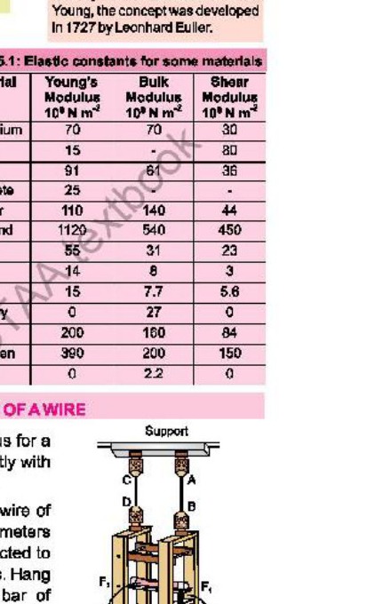
Experimentally, the magnitude of Young's modulus for a material in the form of wire can be found out mostly with help of searl apparatus as shown in Fig.
Construction It consists of two wires, auxiliary or reference wire and test wire (experimental wire) of equal lengths of same material having same diameters attached to a rigid support. Both wires are connected to horizontal bars (frames F1, and F2) at the other ends. Hang a constant weight to the hook of horizontal bar of reference wire and hanger on test wire so that wire remains stretched and free from kinks.
Procedure
The following procedure is adopted for finding Young's modulus of a wire experimentally.
i. Measure the initial length Lo of the wire using a metre scale.
ii. Measure the diameter 'd' of the wire using screw guage. The diameter should be measured at several different points along the wire.
iii. Adjust the spirit level so that it is in horizontal position by turning the micrometer reading to uses it as the reference reading.
iv. Load the test wire with a further weight, the spirit level tilts due to elongation of the test wire.
v. Adjust the micrometer screw to restore the spirit level in the horizontal position subtract the first micrometer readings from the second micrometer reading to obtain the extension of the test wire.
vi. Calculate stress and stain from the following formula:
σ = Stress = weight/area of wire = F/A = mg/πr²
ε = Strain = ΔL/Lo = change in length/original length
vii. Repeat the above steps by increasing load on test wire to obtain more values of stresses and strains.
viii. Plot the above values on stress strain graph it should be straight line, determine value of slope Y, which is equal to young's modulus of the given material.
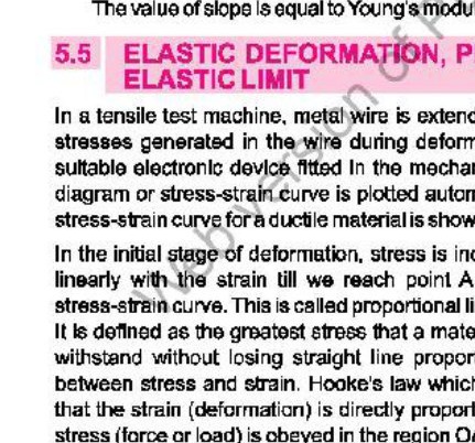
In a tensile test, a metal wire is extended at a specified deformation rate, and the stresses generated in the wire during deformation are continuously measured by a suitable electronic device fitted in the mechanical testing machine. A force-elongation diagram or stress-strain curve is generated automatically on X-Y chart recorder. A typical stress-strain curve for a ductile material is shown in Fig. We discuss the behaviour of different portions of the curve in detail:
From 0 to A
In the initial stage of deformation, stress is increased linearly with the strain till we reach point A on the stress-strain curve. This is called proportional limit (σp).
Proportionality limit
Stress increases linearly with strain until point A is reached on the stress strain curve. This point is called the proportional limit.
Hooke's law which states that the strain (deformation) is directly proportional to stress (force or load) is obeyed in the region OA. From A to B, stress and strain are no longer proportional.
Elastic limit
If the load is removed at any point between O and B, the curve will be retraced and the material will return to its original length. In this region (OB), the material is said to be elastic. The point B is called the yield point. The value of stress at B is known as elastic limit σy.
Plastic Deformation (From B to C)
If the stress is increased beyond the yield stress or elastic limit of the material, the specimen becomes permanently changed and does not recover its original shape or dimension after the stress is removed. This kind of behaviour is called plasticity. The region of plasticity is represented by the portion of the curve from B to C.
Ultimate Tensile strength
The point C in Fig. represents the ultimate tensile strength (UTS) σm of the material. The UTS is defined as the maximum stress that a material can withstand, and can be regarded as the nominal strength of the material.
Fracture stress
Once point C corresponding to UTS is crossed, the material breaks at point D, represents the fracture stress (σf).
Ductile substance
Substances which undergo plastic deformation until they break, are known as ductile substances. For example, lead, copper and wrought iron are ductile substances.
Brittle Substance
The substances which break just after the elastic limit is reached, are known as brittle substances. For example, glass and high carbon steel are brittle. Moreover, Beryllium, Chromium are also brittle metals.
Strain Energy in Deformed Materials
When a body is deformed by a force, work is done against the elastic restoring force. This work is stored in it as its potential energy and is equal to the gain in potential energy of the molecules of a body due to the displacement of these molecules from their mean positions.
Derivation of Expression for Energy Stored in a Stretched Material
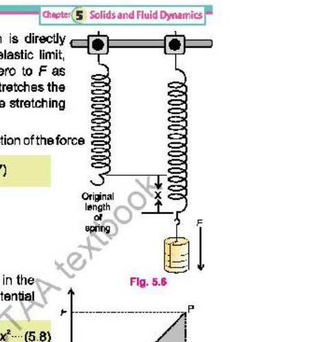
Consider a material in the form of a spring as shown in Fig. It is stretched by a force F through extension x. As the extension is directly proportional to the stretching force within the elastic limit, therefore the force increases uniformly from zero to F as shown in Fig. Thus, the average force that stretches the spring through x is 1/2 F. Hence, the work done by the stretching force will be given as:
Work done = Average force x Distance in the direction of the force
W = 1/2 F x x ----------(1)
Or
W = Area of OPQ
The work done by the stretching force is stored in the spring as its strained energy and is equal to the potential energy stored in its molecules.
From Hooke's law
F = k (x)
Therefore,
W = (1/2 kx).(x) = 1/2 kx²
Strained energy stored in the body = E= 1/2 F. x = 1/2 kx²
Archimedes' Principle and Floatation
Introduction
More than two thousand years ago, the Greek scientist, Archimedes noticed that there is an upward force which acts on an object which is kept inside a liquid. As a result, an apparent loss of weight is observed in the object.
Upthrust
The upward force acting on the object is called the upthrust of the liquid.
Statement
When an object is totally or partially immersed in a liquid, an upthrust force acts on it equal to the weight of the liquid it displaces.
Explanation
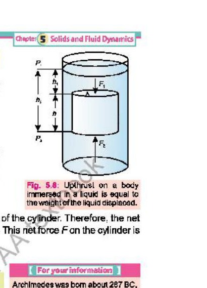
Consider a solid cylinder of cross-sectional area A and height h immersed in a liquid as shown in Fig. Let h1 and be the depths of the top and bottom faces of the cylinder respectively from the surface of the liquid. Then
h2 - h1 = h --------- (1)
If P1 and P2 are the liquid pressures at depths h1 and h2 respectively and ρ is its density, then
P1 = ρgh1A
and
P2 = ρgh2A
Let the F1 be the force exerted at the top of cylinder due to pressure P1 and the force F2 be exerted at the bottom of the cylinder due to P2,
Then
F1 = P1A = ρgh1A
and
F2 = P2A = ρgh2A
Since F1 and F2 are the forces acting on the opposite faces of the cylinder. Therefore, the net force F will be equal to the difference of these forces. This net force F on the cylinder is called the upthrust of the liquid. Hence
F2 - F1 = ρgh2A - ρgh1A
= ρgA(h2 - h1) --------- (2)
Or upthrust liquid = ρgAh ∴ h = h1 - h2
Upthrust = ρgV
Since Ah is the volume V of the cylinder and is equal to the volume of the liquid displaced by the cylinder, therefore, ρgV is the weight of the liquid displaced. This equation shows that an upthrust acts on a body immersed in a liquid is equal to the weight of liquid displaced, which is Archimede's principle.
Note Upthrust = mg (∴ m = ρV) so, upthrust = ρVg
Floatation
An object sinks if its weight is greater than the upthrust force acting on it. However, an object floats if its weight is equal or less than the upthrust. When an object floats in a fluid, the upthrust acting on it is equal to the weight of the object. In case of floatting object, the object may be partially immersed. The upthrust is always equal to the weight of the fluid displaced by the object. This is the principle of floatation. It states that:
A floating object displaces a fluid whose weight is equal to the weight of the object.
Archimedes' principle is applicable to liquids and gases and has numerous applications in daily life.
Applications
Following are some important applications of Archimedes' principle.
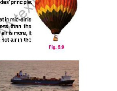
(i) Hot-air balloon
The reason why hot-air balloons rise and float in mid-air is because of the density of the hot-air balloon is less than the surrounding air. When the buoyant force of the hot-air balloon is more, it starts to rise. This is done by varying the quantity of hot air in the balloon.
(ii) Wooden block floating on water
A wooden block floats on water. It is because the weight of an equal volume of water is greater than the weight of the block. According to the principle of floatation, a body floats if its displaced water is equal to the weight of the body when it is partially or completely immersed in water.
(iii) Ships and boats
Ships and boats are designed on the same principle of floatation. They carry passengers and goods over water. It would sink in water if its weight including the weight of passengers and goods becomes greater than the upthrust of water.
(iv) Submarine
A submarine can travel over as well as under water using the same principle of floatation.
It floats over water when the weight of water equal to its volume is greater than its weight. Under this condition, it is similar to a ship and remains partially above water level. It has a system of tanks which can be filled with and emptied from seawater. When these tanks are filled with seawater, the weight of the submarine increases. As soon as its weight becomes greater than the upthrust, it dives into water and remains under water. To come up on the surface, the tanks are made empty from seawater.
Moving fluids have great importance. In order to find the behaviour of the fluid in motion, we consider their flow through the pipes. When a fluid is in motion, its flow can take place in two ways, either streamline or turbulent.
Streamline or Laminar Flow
Definition "The flow is said to be streamline or laminar flow if every particle that passes a particular point, never deviates from its course and moves along exactly the same path, as followed by particles which passed that points earlier."
Explanation In a steady flow of a fluid, the motion of the particles is smooth and regular as shown in Fig. The smooth path followed by fluid particles in laminar flow is called a streamline. The streamline may be the straight or curved and tangent to any point gives the direction of flow of a fluid. The different streamlines cannot cross each other.
Example A fluid flowing in a pipe as shown in Fig. will have certain velocity v₁ at P, a velocity v₂ at Q and so on. If the velocity of a particle of the fluid at P, Q and R does not change with the passage of time, then the flow is said to be steady flow or streamline flow. The line PQR which represents the path followed by the particle is called a streamline. It represents the fixed path followed by orderly processing particles. In streamline flow, all the particles passing through P also pass through Q and R. It means that two streamlines cannot cross each other.
Turbulent Flow
Definition "The irregular or unsteady flow of the fluid is called turbulent flow."
Explanation Above a certain velocity of the fluid flow, the motion of the fluid becomes unsteady and irregular. Under this condition, the velocity of the fluid changes abruptly as shown in the Fig. In this case, the exact path of the particles cannot be considered. If two streamlines cross each other, then the particles will go in one or in the other directions and flow will not be a steady flow. When the flow is unsteady or turbulent, there are eddies and whirlpools in the motion and the paths of the particles are continuously changing.
Rate of Flow
The rate of flow of a fluid through a pipe is the volume of the fluid passing through any section of pipe per unit time.
Formula for Rate of Flow:
Consider a fluid flowing through a pipe of area of cross-sectional A as shown in Fig. Let the velocity of the fluid be v and it flows through the pipe for time t, then the distance covered by the fluid in time is:
ℓ = vt
where ℓ is the length of the pipe through which the fluid passes in time t. Volume of the fluid passing through the pipe in time t, is:
A × ℓ = Avt
Thus The rate of flow of the liquid = Volume / Time
= Avt / t = Av
Rate of flow = Av
In SI units, it is measured in cubic metre per second (m³ s⁻¹). Sometimes, it is also measured in litres per second (Ls⁻¹).
Steady Flow
If the overall flow pattern does not change with time, the flow is called steady flow. In steady flow, every particle of the fluid follows the same flow line as its previous particle.
The behaviour of the fluid which satisfies the following conditions is called ideal fluid:
i. The fluid is non-viscous i.e., there is no frictional force between adjacent layers of the fluid.
ii. The fluid is incompressible i.e., its density is constant.
iii. The fluid motion is steady.
Equation of Continuity
Statement The product of cross-sectional area of the pipe and the fluid speed at any point along the pipe is constant. This constant equals the volume flow per second of the fluid or simply the flow rate.
Explanation Let A₁, v₁ and ρ₁ are area of cross-section, uniform velocity and density of the fluid at the lower end respectively. Similarly let A₂, v₂ and ρ₂ are area of cross-section uniform velocity and density of the fluid at upper end respectively of the pipe as shown in Fig. The pipe is of non-uniform area of cross section.
Suppose distances covered by the fluid in the lower and upper ends of the pipe are Δx₁ and Δx₂, during Δt time.
Where by using the formula (s = vt) we have
Δx₁ = v₁ Δt
Δx₂ = v₂ Δt
Volume of the fluid entered through the lower end of the pipe is the volume of the pipe shown at the bottom.
∴ V₁ = A₁Δx₁
∴ V₁ = A₁v₁Δt
Now Δm₁ = mass entered in time Δt
Δm₁ = density × volume
Δm₁ = ρ₁ A₁v₁ Δt ---------- (1)
Similarly, volume of the fluid flown out of the upper end of the pipe is again volume of the pipe shown at the top.
∴ V₂ = A₂ Δx₂ ∴ Δx₁ = v₁Δt
∴ V₂ = A₂ v₂ Δt
Thus
Δm₂ = mass flown out in time Δt
Δm₂ = density × volume
Δm₂ = ρ₂ A₂ v₂ Δt ---------- (2), (As w₂ is taken negative because work is done against the opposing fluid.)
Using law of conservation of mass for streamline flow we have
Δm₁ = Δm₂
Put values from equations (1) and (2)
ρ₁ A₁v₁ Δt = ρ₂ A₂v₂ Δt
⟹ ρ₁ A₁v₁ = ρ₂ A₂v₂
This equation is called equation of continuity.
During streamline flow the fluid is incompressible then its density remains constant. So we can put ρ₁ = ρ₂ = ρ in above equation.
ρA₁v₁ = ρA₂v₂
A₁v₁ = A₂v₂ ---------- (3)
OR
Av = constant
This equation is also called the equation of continuity which is applicable for steady flow of an ideal flow. In other words, this equation can be stated as below:
The product of cross-sectional area of the pipe and the fluid speed at any point along the pipe is constant. This constant equals the volume flow per second of the fluid or simply the flow rate.
In other words, we can say that "The rate of flow of an ideal fluid during streamline flow remains constant".
Increase in Flow Velocity
We can increase the flow velocity of water in a rubber pipe by squeezing it. When we squeeze the rubber pipe, we decrease the cross-sectional area through which the water flows. According to the equation of continuity,
A₁v₁ = A₂v₂
where A is the cross-sectional area and v is the flow velocity. By decreasing the cross-sectional area (A₂ < A₁), the velocity of the water (v₂) must increase to maintain the same flow rate. Therefore, squeezing the rubber pipe increases the flow velocity of water.
Bernoulli's Equation
Statement "The sum of pressure, K.E per unit volume and P.E per unit volume of an ideal fluid during streamline flow remains constant throughout the pipe".
Explanation Consider an ideal fluid in a streamline flow in the pipe as shown in Fig. Let A₁ is the area of cross-section of the top end of the pipe whose height is h₁ from the reference surface. The uniform fluid speed at the top end is v₁. Suppose the pressure P₁ pushes the fluid inside through a distance Δx₁. Therefore, work done on the fluid in-pushing it into the pipe through distance Δx₁.
W₁ = F̄.Δx₁
= F₁Δx₁ cos 0° ∴ F₁ = P₁A₁
Therefore W₁ = P₁A₁ v₁t ---------- (1) ∴ Δx₁ = v₁t
Now suppose A₂ is the area of cross-section of the lower end where speed of the fluid is v₂. The fluid already present at the lower end exerts pressure P₂ on the fluid coming from the upside. Let the fluid coming from the upside travels a distance of Δx₂ in a time t in the presence of the inward pressure P₂. So work done on the fluid at the lower end
W₂ = F̄₂.Δx₂
⟹ W₂ = F₂Δx₂ cos 180°
Where cos 180° = - 1, Δx₂ = v₂t and F₂ = P₂A₂
Therefore, W₂ = - P₂A₂ v₂t ---------- (2)
By law of conservation of energy, the total work done on the fluid as it passes from top to the bottom is equal to the change in K.E plus change in P.E.
Therefore w = Δ(K.E) + Δ(P.E)
⟹ W₁ + W₂ = (½ mv₂² - ½ mv₁²) + (mgh₂ - mgh₁)
Put values from equations (1) and (2) in left hand side we get
P₁A₁v₁t - P₂A₂ v₂t = (½ mv₂² - ½ mv₁²) + (mgh₂ - mgh₁)
Where
A₁v₁t - A₂v₂t = Volume of fluid flown in time t = V
P₁ V - P₂ V = (½ mv₂² - ½ mv₁²) + (mgh₂ - mgh₁)
V(P₁ - P₂) = (½ mv₂² - ½ mv₁²) + (mgh₂ - mgh₁)
Dividing both sides by 'V' (volume):
P₁ - P₂ = ½ m/V v₂² - ½ m/V v₁² + m/V gh₂ - m/V gh₁
Here by definition m/V = ρ
Therefore, P₁ - P₂ = ½ ρv₂² - ½ ρv₁² + ρgh₂ - ρgh₁
P₁ + ½ρv₁² + ρgh₁ = P₂ + ½ρv₂² + ρgh₂ ---------- (3)
OR In general form,
P + ½ρv² + ρgh = constant ---------- (4)
The equation (3) in the box is known as Bernoulli's equation in fluid dynamics. Eq. (4) is its in general form.
Uses of Bernoulli's Principle
A number of devices operate by means of pressure difference that results from changes in the speed of the fluid.
i. Aeroplane Wings
The wing of an aeroplane is designed to deflect the air so that streamlines are closer together above the wing than below it as illustrated in Fig. We have seen that where the streamlines are forced closer together, the speed is faster. Thus, air is travelling faster on the upper side of the wing than on the lower. The pressure will be lower at the top of the wing, and the wing will be forced upward and the lift of an aeroplane is due to this effect.
ii. Swing of a Ball
When a ball is thrown or kicked with spin, the ball is made smoother on one side by the bowler and remains rough on the other side. The air moves slower over rough side and faster over the smoother. According to Bernoulli's equation, the faster moving air creates lower pressure, while the slower moving air creates higher pressure, this pressure difference generates a sideways force, known as Magnus effect which causes the ball to curves in the air.
iii. Filter Pump
A filter pump has a constriction in the centre, so that a jet of water from the tap flows faster here and near it and air, therefore, flows in from the side tube. The air and water together are expelled through the lower part of the pump.
iv. Carburetor
The carburetor of a car engine uses a Venturi duct to feed the correct mixture of air and petrol to the cylinders. Air is drawn through the duct and along a pipe to the cylinders. A tiny inlet at the side of duct is fed with petrol.
The air through the duct moves very fast, creating low pressure in the duct, which draws petrol vapours into the airstream.
v. Paint Sprayer
A stream of air passing over a tube dipped in a liquid will cause the liquid to rise in the tube as shown in Fig. This effect is used in perfume bottles and paint sprayers. In fact when the rubber ball of atomizer is squeezed, the air is blown through tube and it rushes out through a narrow aperture with high speed and it causes a fall in pressure. Therefore, the atmospheric pressure pushes the perfume up, leading to the narrow aperture.
vi. Venturi Relation
Consider a pipe within which a fluid of density ρ is flowing through different areas of cross-section as shown in the Fig.
Let A₁ be the cross-sectional area at wide end and A₂ be the cross-sectional area at narrow portion. Suppose that v₁ and v₂ be the flow speeds at the wide and narrow portions respectively. Pressure P₁ and P₂ indicate the liquid pressure at both the portions by connecting the limbs of the manometer.
Since the pipe is placed horizontally, therefore, we consider that average potential energy is the same at both places while using Bernoulli's equation.
Thus, Bernoulli's equation can be written as:
P₁ + ½ρv₁² = P₂ + ½ρv₂²
or P₁ - P₂ = ½ρv₂² - ½ρv₁²
or P₁ - P₂ = ½ρ(v₂² - v₁²) ---------- (1)
From the equation of continuity:
A₁v₁ = A₂v₂
or v₁ = A₂v₂/A₁
As the cross-sectional area A₂ is small as compared to the area A₁ as is clear from the figure, i.e. A₂ < A₁. So, v₁ will be small as compared to v₂. Thus, the speed of the fluid is very slow in wider portion of the pipe as compared to the narrow portion. So, we can neglect v₁ on the right-hand side of Eq. (1). Hence
P₁ - P₂ = ½ρv₂² ---------- (2)
This is known as Venturi relation, which is used in venture meter, a device used to measure speed of liquid flow.
Torricelli's Theorem
Ans. Torricelli's theorem
Statement "The speed of efflux of the fluid is equal to the velocity gained by it as it falls through the height 'h' under the action of gravity":
veff = √(2gh)
Where h = h₁ - h₂
veff = √(2g(h₁ - h₂))
Proof Consider a fluid in a tank with small hole in its wall as shown in Fig. Let A₁ is the area of Cross-sectional of the top face of tank and A₂ is the area of cross-section of hole or orifice.
Using Bernoulli's equation, we have:
P₁ + ½ρv₁² + ρgh₁ = P₂ + ½ρv₂² + ρgh₂
In above situation we have P₁ = P₂ = Pa = atmospheric pressure.
Therefore Pa + ½ρv₁² + ρgh₁ = Pa + ½ρv₂² + ρgh₂
⟹ ½ρv₁² + ρgh₁ = ½ρv₂² + ρgh₂
⟹ ρgh₁ - ρgh₂ = ½ρv₂² - ½ρv₁²
⟹ ρg(h₁ - h₂) = ½ρ(v₂² - v₁²)
As A₁ >> A₂ which implies v₁<< v₂, so we can neglect v₁² in the right hand side of the above equation.
Therefore g(h₁ - h₂) = ½v₂²
⟹ v₂² = 2g(h₁ - h₂)
Take square root on both sides we get
v₂ = √(2g(h₁ - h₂))
This is the proof of Torricelli's theorem.
(i) Viscosity
Definition "The frictional effect between different layers of a flowing fluid is called viscosity of the fluid."
Explanation Viscosity measures, how much force is required to slide one layer of the liquid over another layer. Substances that do not flow easily, such as thick tar and honey, etc., have large coefficients of viscosity, usually denoted by Greek letter 'η'. Substances which flow easily, like water, have small coefficient of viscosities. Since liquids and gases have non zero viscosity, therefore, a force is required if an object is to be moved through them. Even the small viscosity of the air causes a large retarding force on a car as it travels at high speed. If you stick out your hand out of the window of a fast-moving car, you can easily recognize that considerable force has to be exerted on your hand to move it through the air.
(ii) Drag Force
An object moving through a fluid experiences a retarding force called a drag force. The drag force increases as the speed of the object increases.
Even in the simplest cases, the exact value of the drag force is difficult to calculate. However, the case of a sphere moving through a fluid is of great importance.
(iii) Stoke's Law:
"For a spherical body of radius 'r' moving slowly with velocity 'v' in a fluid of viscosity 'η' the force on the spherical body is given by the following formula
F = 6πηrv
This equation is known as Stoke's law because it was formulated by Stoke named after George Grabriel Stokes
It may be remembered that at high speeds the drag force is not proportional to speed of the body.
Terminal Velocity
Definition "When an object is falling in a fluid then its maximum and constant velocity in that fluid is known as terminal velocity of the object". An object achieves terminal velocity when its weight becomes equal to the drag force of the viscous medium in which it is moving.
Explanation Consider a spherical water droplet like that of fog slowly falling vertically down. Two forces will be acting on it:
(i) Weight force of droplet = mg
(ii) Drag force of air = 6πηrv
The not force on the droplet in the vertically downward direction is:
Net force = Weight - Drag force
⟹ F = mg - 6πηrv -----(1)
Because of its weight the downward velocity of the droplet increases, which implies an increase in the drag force. Eventually, a stage comes when drag force becomes equal to the weight. In this state the net force on the droplet becomes zero and hence no further increase in the velocity of droplet occurs. So this velocity is the maximum and constant velocity is known as Terminal Velocity 'vt' of the droplet.
Thus above equation (1) becomes as written below:
0 = mg - 6πηr vt
⟹ 6πηr vt = mg
⟹ vt = mg / 6πηr ---------- (2)
If g/6πηr = constant, then vt = constant × m
∴ vt ∝ m
This shows terminal velocity is directly proportional to mass of the spherical droplet of constant radius.
This formula can also be written in another form as below:
Since m = density × volume
⟹ m = ρ × 4/3 πr³
Here ρ is the density of the droplet.
Substituting this value in above equation (2) we get
vt = (4ρπr³/3) × (g/6πηr)
⟹ vt = 2ρgr² / 9η -----(3)
Here 2ρg/9η = constant
vt = constant × r²
∴ vt ∝ r²
This shows that terminal velocity is directly proportional to the square of the radius of the spherical droplet. Equations (2) and (3) are the formulas for the terminal velocity of a spherical object falling in vacuum. If the object is falling in a vacuum, η = 0, and hence the terminal velocity becomes infinite, as there is no drag force.
Ideal Fluid
It is a fluid that does not have viscosity and cannot be compressed. This type of fluid cannot exist practically and is only used in theoretical models.
Real fluid
All types of fluids that possess viscosity are classified as real fluids.
Examples Kerosene and castor oil, honey, etc.
Explanation An example of ideal fluid cannot be provided because it does not exist in the real world but only in theory. However, every fluid that we see around us like water, diesel, petrol, honey, etc. are real fluids. Moreover, differences in viscosity can be found in real life, for example, honey is more viscous than water. Bernoulli's equation states that the speed of fluid flow is increased as a result of a simultaneous decrease in the potential energy of the fluid or a decrease in the static pressure on the fluid. When a fluid is viscous, it essentially notes to the thickness of the fluid or the friction the fluid faces while fluid flows. Therefore, ideal fluids do not face the opposing force and have a non-viscous flow, while real fluids have a viscous flow.
Key difference between ideal and real fluids:
i. Compressibility:
• Ideal fluids are incompressible (density and volume do not change with pressure).
• Real fluids are compressible to some extent.
ii. Bulk modulus:
• For ideal fluids, volume change is zero, so the bulk modulus is infinite.
• Real fluids have finite bulk modulus due to compressibility.
iii. Surface tension:
• Ideal fluids are not subjected to surface tension.
• Real fluids exhibit surface tension.
iv. Viscosity
• Ideal fluids do not have any viscosity or can be said to have zero viscosity. Moreover,
• Real fluids have viscosity.
Superfluidity
Superfluidity is a property of fluids where they have zero viscosity or are frictionless. A substance exhibiting this property is superfluid. Superfluids flow without loss of kinetic energy. In the laboratory, superfluids form in some substances at cryogenic temperature, not much above absolute zero.
Superfluids can flow through incredibly narrow spaces without any resistance. They can defy gravity and flow upwards against it as shown in Fig.
Properties of Superfluids
Superfluids exhibits unique behaviour not seen in regular fluids and gases. For instance, helium-3 can climb container walls and escape, a phenomenon known as film flow, and can even pass through container walls. When stirred, superfluids create persistent vortices, unlike regular fluids that settle. Interestingly, when a container of superfluid is rotated, the liquid inside remains still, unlike typical fluids that rotate with container. Superfluids consist of a mixture of normal and superfluids components, with more superfluid present at lower temperatures. Some superfluids have high thermal conductivity and varying compressibility. It is important to note that superfluidity differs from superconductivity; for example, both superfluids helium-3 and helium-4 do not conduct electricity.
Examples of Superfluids
Superfluids helium-4 is the most studied example of superfluidity. It changes from a liquid to a superfluids just a few degrees below its boiling point of-452°F (-269°C or 4 K). Superfluids helium-4 moving as a normal clear liquid, but it has no viscosity. This means that once it starts to flow, it continues to move past any obstacles.
Here are other superfluidity examples:
• Superfluid helium-3
• Some Bose Einstein condensates as superfluids (not all, though)
• Atomic rubidium-85
• Lithium-6 atoms (at 50 nK)
• Atomic sodium
• Possibly inside neutron stars
Superfluidity Applications
i. Currently, there are few practical uses for superfluids. Superfluid helium-4 serves as a coolant for high-field magnets. Both helium-3 and helium-4 are utilized in advanced particle detectors.
ii. Researching superfluidity also helps us learn more about superconductivity.
iii. Liquid helium is recognized for its great thermal conductivity and is used in cryogenic applications, including cooling superconducting magnets, scientific research, and medical uses.
iv. Additionally, it is employed in industry for leak testing and in the production of electronic and optical products.
More figures from this unit