StudentAid
Unit 9: Electrostatics and Current Electricity — Long Questions
11th Class Physics · Unit 9: Electrostatics and Current Electricity
Electrostatics
Definition: "It is the branch of physics which deals with electric forces when the charges are at rest"
A positively charged body is one which loses electrons and a negatively charged body is one which gain electrons. The electrons are negatively charged and protons are positively charged. Also like charges repel each other and unlike charges attract each other. The SI unit of charge is coulomb. One coulomb is equal to the charge of 6.25 × 10¹⁸ electrons.
Electric Force:
Definition: "The force due to which charged particles attract or repel each other is called electric force" This force is responsible for the stability of atoms and molecules of which the whole matter is composed.
(a) Coulomb's Law:
This law was explained in 1874 by French army engineer Charles Coulomb experimentally. It relates with interaction between static charges.
Statement:
"It states that the force of attraction or repulsion between two point charges is directly proportional to the product of charges and inversely proportional to the square of distance between them"
Explanation:
If two point charges q1 and q2 are separated by a distance r then.
F ∝ q1q2 --------- (1)
F ∝ 1/r² ----------- (2)
By combining these results (1) and (2)
F ∝ q1q2/r²
F = K q1q2/r²
Where K is constant of proportionality. Its value depends upon the system of units and nature of the medium between two point charges. If the system is SI and the medium is free space. Then
K = 1/(4πε₀)
Where ε₀ is the permittivity of free space. Its value is 8.85 × 10⁻¹² C²/Nm²
K = 1/(4 × 3.14 × 8.85×10-12 C²/Nm²)
We get K = 9×10⁹ Nm²/C²
Thus Coulomb force in free space is written as
F = 1/(4πε₀) × q1q2/r² --------(i)
Vectorial form of Coulomb's law:
As force is a vector quantity, therefore we may write it in vector from
F⃗ = 1/(4πε₀) × q1q2/r² r̂ ------------(ii)
Where r̂ is unit vector showing direction of force.
If we denote the force exerted on q2 by q1 as F21 then according to Coulomb's law.
F⃗21 = 1/(4πε₀) × q1q2/r² r̂21 ------------(iii)
Where r̂21 is a unit vector directed from q1 to q2 in the direction of F⃗21
Similarly, there force exerted on q1 by q2 is F̂12
F̂12 = 1/(4πε₀) × q1q2/r² (-r̂12) --------- (iv)
Where r̂12 is a unit vector in the direction of F̂12
As r̂12 = -r̂21 (From Fig.)
Hence, Eq. (iv) becomes.
F̂12 = 1/(4πε₀) × q1q2/r² (-r̂12)
F̂12 = -[1/(4πε₀) × q1q2/r² r̂12]
Using Eq. (iii) we get
F̂12 = -F̂21
Conclusion:
Coulomb's force is a mutual force. It means that if q1 exerts a force on q2 then q2 also exerts an equal but opposite force on q1. This shows that action and reaction are equal in magnitude but opposite in direction. Thus Coulomb's law is in accordance with third law of motion.
(b) Effect of Dielectric:
It has been experimentally observed that if a dielectric medium is introduced between the two point charges, then coulomb force between them decreases by a certain factor which is called the dielectric constant εr, i.e.
F' = 1/(4πε₀εr) × q1q2/r²
F' = 1/εr (1/(4πε₀) × q1q2/r²)
F' = 1/εr F
As the value of εr is always greater than one (except for air εr =1)
Hence, F' < F
εr = F/F'
Relative permittivity of a medium can be defined as the ratio of force between two charges placed in air or vacuum to the force when they are placed in the dielectric medium. It has no unit because it is a ratio between two similar quantities.
Electric Intensity
Definition:
It is the force experienced by a test charge q0 placed at a certain point in that field i.e.
It is the force per unit charge i.e. E⃗ = F⃗/q₀
It is a vector quantity and directed in the direction of force. Its unit is N/C or V/m.
Explanation:
Electric intensity is a force, so it is a vector quantity and is usually denoted by E. It can be obtained by the relation:
E = F/q ----------(i)
As F = 1/(4πε₀) × qQ/r²
E = 1/(4πε₀) × qQ/(q₀r²)
E = 1/(4πε₀) × Q/r²
In vector form:
E⃗ = 1/(4πε₀) × Q/r² r̂
From Eq. (i), the unit of electric intensity is newton per coulomb N C⁻¹. The direction of E is same as that of F. The Eq. (i) can be written as:
F⃗ = q E⃗ --------(ii)
Electric field lines
These are the imaginary lines present in an electric field proposed by Michael Faraday. The direction of the electric field lines is always away from positive charge i.e. the line along which a test charge i.e. unit positive charge will move on an electric field.
Explanation
(i) Field pattern of positive charge:
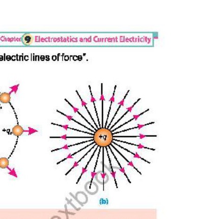
If test charges are placed around a charge q such that they are at equidistant from the charge q then each test charge will be repelled by the charge q and will radially move outward.
Hence electric lines of force due to positive charge are radially directed away from it.
(ii) Field pattern of negative charge:
In case of negative charge, the field lines will be directed inward, because of attractive force which is directed inward.
The number of lines per unit area passing perpendicularly through it is proportional to the magnitude of the electric field.
(iii) Electric field pattern of two identical charges:
The electric field lines are curved in case of two identical separated charges. Fig. shows the pattern of lines associated with two identical positive point charges of equal magnitude. It reveals that the lines in the region between two like charges seem to repel each other. The behaviour of two identical negatively charges will be exactly the same. The middle region shows the presence of a zero field spot or neutral zone.
(iv) Electric field pattern of two opposite charges:
Fig. shows the electric field pattern of two opposite charges of equal magnitudes. The field lines start from positive charge and end on a negative charge. The electric field at points such as 1, 2, 3 is the resultant of fields created by the two charges at these points. The directions of the resultant intensities are given by the tangents drawn to the field lines at these point.
In the regions where the field lines are parallel and equally spaced, the same number of lines pass per unit area and therefore, field is uniform on all points. Fig. shows the field lines between the plates of a parallel plate capacitor. The field is uniform in the middle region where field lines are equally spaced.
Characteristics of electric field lines:
i. Electric field lines start from positive charge and terminate at negative charge.
ii. The tangent to the field lines at any point gives the direction of electric intensity at that point.
iii. If the lines are closer the field is strong and if lines are far apart the field is weak
iv No two lines cross each other because E has only one direction at one point
Electric Flux
Definition:
"The number of electric field lines passing through a certain element of area is called electric flux."
Explanation:
It is numerically equal to the scalar product of electric field intensity (E⃗) and vector area (A⃗)
Symbol: It is denoted by
φₑ (Greek letter phi)
Mathematically:
φₑ = E⃗.A⃗
Unit: its SI unit is N/C × m² = Nm²/C
Nature of Quantity:
As electric flux is a scalar product, therefore, it is a scalar quantity.
Illustration with example:
The flux (φ) through the area A as shown in Fig. is 4 while the flux through B is 2.
Special Cases:
(i) Maximum flux:
When surface area is perpendicular to the lines of electric force or its vector area is along the direction of electric lines of force, then value of electric flux is maximum and is given by:
∴θ = 0°
φₑ = E⃗.A⃗
= EAcosθ
= EAcos0°
= EA(1)
φ = EA
(ii) Minimum flux:
When surface area is parallel to the lines of electric force, or its vector area is perpendicular to the lines of electric force then electric flux passing through it is minimum (zero).
∴θ = 90°
φₑ = E⃗.A⃗
= EAcos90°
= EA(0)
φ = 0 (Minimum)
(iii) When the area vector A makes angle θ with the field line (general case).
When A is neither perpendicular nor parallel to field lines but is inclined at an angle θ with the field E⃗. In this case, we have to find the projection of the area which is perpendicular to the field lines. The area of this projection shown in Fig. is A cosθ. The flux φₑ in this case is:
φₑ = E⃗.A⃗
= EAcosθ
Note:
(i) The term flux is a Latin word referring to something that can flow. For example, flux of water, flux of field, flux of light etc.
(ii) The vector area of a given surface is a vector whose magnitude is always equal to an area and its direction is always perpendicular to the given surface.
Mathematically:
ΔA⃗ = |ΔA|n̂
Where |ΔA|= magnitude
n̂ = unit vector showing direction along the outword drawn normal to the surface
(iii) In case of a closed surface like balloon, the whole surface is defined into small patches which are so small that over any patch the surface area is practically flat.
(iv) Electric flux linked with a surface gives an idea of the number of electric lines of force passing through the surface.
Electric Flux Through a Closed Surface (Sphere):
Consider a charge q is placed at the centre of a sphere of radius r in order to find the electric flux through this closed surface. It is divided into a large number of surface elements. Such that each element is nearly flat. The flux through each element is determined and added i.e.
φ₁ = E⃗₁.ΔA⃗₁
φ₂ = E⃗₂.ΔA⃗₂
φ₃ = E⃗₃.ΔA⃗₃
φ₄ = E⃗₄.ΔA⃗₄
φ₅ = E⃗₅.ΔA⃗₅
-----
φₙ = E⃗ₙ.ΔA⃗ₙ
The flux through the whole sphere will be.
φₑ = φ₁ + φ₂ + φ₃ + φ₄ + φ₅ + --------- φₙ
φₑ = E⃗₁.ΔA⃗₁ + E⃗₂.ΔA⃗₂ + E⃗₃.ΔA⃗₃ + E⃗₄.ΔA⃗₄ + E⃗₅.ΔA⃗₅ + --------- + E⃗ₙ.ΔA⃗ₙ
For each element the angle between E⃗ and ΔA⃗ is 0°.
φₑ = E₁.ΔA₁ cos 0° + E₂.ΔA₂ cos 0° + E₃.ΔA₃ cos 0° + E₄.ΔA₄ cos 0° + E₅.ΔA₅ cos 0° ------- Eₙ.ΔAₙ cos 0°
As each area element is at equal distance form q.
E₁ = E₂ = E₃ = E₄ = ------ Eₙ = E = 1/(4πε₀) × q/r²
φₑ = E{ΔA₁ + ΔA₂ + ΔA₃ + ΔA₄ + ------ ΔAₙ}
φₑ = E[Σ(i=1 to n) ΔAᵢ] = E × (Surface area of sphere).
φₑ = 1/(4πε₀) × q/r² [4πr²]
φₑ = q/ε₀
This is electric flux through a sphere enclosing a charge q at its centre.
We can conclude that total flux through a closed surface does not depend upon the shape or geometry of the closed surface.
Electric flux depends upon the flowing factors:
• Medium
• Charge enclosed
Gauss's Law
Statement: "It states that flux through any closed surface is 1/ε₀ times the total charge enclosed by the closed surface"
i.e.
φₑ = 1/ε₀ × Q
Explanation:
Consider a closed surface 'S' enclosing a number of point charges and imagine small sphere around each charge. The flux through each sphere is calculated and added to get the net flux.
The electric flux due to charge q₁ is
φ₁ = q₁/ε₀
Similarly, the electric flux due to all the charges will be
φ₂ = q₂/ε₀, φ₃ = q₃/ε₀, φ₄ = q₄/ε₀, φ₅ = q₅/ε₀, ------ φₙ = qₙ/ε₀
The total flu through entire closed surface is the sum of electric fluxes due to all the point charges.
φₑ = φ₁ + φ₂ + φ₃ + φ₄ + φ₅ + --------- φₙ
φₑ = q₁/ε₀ + q₂/ε₀ + q₃/ε₀ + q₄/ε₀ + q₅/ε₀ + -------+ qₙ/ε₀
φₑ = 1/ε₀ {q₁ + q₂ + q₃ + q₄ + q₅ + ------- +qₙ}
Where
Q = q₁ + q₂ + q₃ + q₄ + ------ +qₙ (Total charge enclosed by the closed surface)
φₑ = 1/ε₀ × Q
It means that electric flux through any closed surface is 1/ε₀ times the total charge enclosed.
Gaussian Surface
Imaginary closed surface which passes through the point at which the electric intensity is to be evaluated. This closed surface is known as Gaussian surface. Its choice is such that the flux through it can be easily evaluated.
The Field of a Charged Conducting Sphere
Consider a conducting sphere of radius R containing a charge q. We know that all the charge is distributed uniformly over the surface of sphere as shown in Fig. We can also conclude from the spherical symmetry that the electric field is radial everywhere and that its magnitude depends only on the distance r from the centre of the sphere. Thus, the magnitude E is uniform over a spherical surface with any radius r concentric with the spherical conductor.
Therefore, we take our Gaussian surface as an imaginary sphere with radius r"greater than the radius R of the conducting sphere.
The area of the Gaussian sphere is 4πr², and because E is uniform over the sphere, the total flux through the whole surface will be.
Electric flux φₑ = EA = E × 4πr²
∴ A = 4πr²
By Gauss's law,
Total flux EA = q/ε₀
φₑ = q/ε₀
Therefore E × 4πr² = q/ε₀
or E = q/(ε₀ 4πr²)
or E = 1/(4πε₀) × q/r²
This shows that the field at any point outside the sphere is the same as though the entire charge were concentrated at its centre. Just outside of the sphere, where r = R. i.e.
E = 1/(4πε₀) × q/R² ----------(9.15)
In vector form;
E⃗ = 1/(4πε₀) × q/R² r̂ Where r̂ is the direction of E⃗.
Potential Difference
Definition:
It is work done per unit charge to move a charge from one point to another by keeping the charge in electrostatic equilibrium.
Mathematically:
ΔV = Potential difference = work/charge = W/q
Explanation:
Consider a positive charge q which is allowed to move in this uniform electric field. The positive charge will move from plate B to A and will gain K.E. If it is to be moved from A to B, an external force is needed to make the charge move against the electric field and will gain P.E. Let us impose a condition that as the charge is moved from A to B, it is moved keeping electrostatic equilibrium, i.e., it moves with uniform velocity. This condition could be achieved by applying a force F equal and opposite to qE at every point along its path. The work done by the external force against the electric field increases electrical potential energy of the charge that is moved.
Let WAB be the work done by the force in carrying the positive charge q from A to b while keeping the charge in equilibrium. The change in its potential energy ΔU = WAB
or UB - UA = WAB --------(1)
Where UA and UB, are defined to be the potential energies at points A and B. respectively.
So, the potential difference is
ΔV = WAB/q₀ = ΔU/q₀
Potential difference:
The potential difference between two points Aand B in an electric field is defined as the work done in carrying a unit positive charge from A to B while keeping the charge in equilibrium, i.e.,
ΔV = VB - VA = WAB/q = ΔU/q ----------(2)
(OR)
The potential difference between the two points can be defined as the difference of the potential energy per unit charge.
SI Units:
The SI unit of potential difference is joule per coulomb. It is called volt such that,
1volt = 1 joule/1 coulomb ----------(3)
A potential difference of 1 volt exists between two points if work done in moving a 1 coulomb positive charge from one point to the other, keeping equilibrium is one joule.
Electric Potential or Absolute Potential
The electric potential at any point in an electric field is equal to the work done in bringing a unit positive charge from infinity to that point keeping it in equilibrium. So, the potential at a point is always relative to potential at infinity.
Explanation
ΔV = WAB / q
VB - VA = WAB / q
If we take point A to be at infinity and choose VA = 0 , the electric potential at B will be
VB - 0 = W_∞B / qo
In general
V = W / q
Potential difference The potential difference between two points A and B in an electric field is defined as the work done in carrying a unit positive charge from A to B while keeping the charge in equilibrium, i.e.,
ΔV = VB - VA = WAB / q = Δu / q ---------(2)
(OR)
The potential difference between the two points can be defined as the difference of the potential energy per unit charge.
SI Units The SI unit of potential difference is joule per coulomb. It is called volt such that,
1 volt = 1 joule / 1 coulomb ---------(3)
A potential difference of 1 volt exists between two points if work done in moving a 1 coulomb positive charge from one point to the other, keeping equilibrium is one joule.
Electric Field as potential Gradient:
As potential difference between two plates is,
VB - VA = WAB / qo ---------(1)
As WAB = F.d = qo.E.d ∴ F = qo.E
WAB = qo Ed cos θ
∴ WAB = qo Edcos(180°)
Where θ = 180° because E and d are in opposite direction.
ΔV = WAB / qo = -Ed
E = -ΔV / d
If the distance between two plates is very small i.e. Δr then ∴ d = Δr
ΔV / Δr = potential gradient
E = - ΔV / Δr
-ΔV / Δr is maximum rate of decrease of potential with displacement and is called potential gradient. Hence electric intensity is also equal to negative of potential gradient.
SI Units It can be expressed in SI unit as volt/metre. It can be shown that 1Vm-1 = 1 NC-1 as follows:
1 volt / 1m = 1J / 1C / 1m = 1N.1m / 1C.1m = 1N / 1C
1 volt / 1m = 1N / 1C
The negative sign shows that electric field is always in the direction of decreasing potential.
Electron volt
Definition of electron volt "It is the energy acquired or lost by an electron when it moves from one point to other point through a potential difference of 1 volt"
Explanation When a charge particle 'q' moves from A with potential 'VA ' to point 'B' with potential 'VB' keeping electrostatic equilibrium then change of P.E is given by
ΔU = qΔV
In the absence of any external force (dissipative force) then change in P.E appear in the form of gain in K.E.
Δ(K.E) = ΔU = q ΔV
When a charge particle is accelerated through a certain potential difference then if Δv = 1 volt and q = charge of on electron = e = 1.6 × 10⁻¹⁹ C.
Then
1 eV = 1 volt × 1.6 × 10⁻¹⁹ C.
1 eV = 1.6 × 10⁻¹⁹ C × volt
1 eV = 1.6 × 10⁻¹⁹ joule
Its multiples are
1 Mev = 106 eV
1 Kev = 103 eV
Motion of charged particles in a uniform electric field
Two oppositely charged parallel metal plates produce uniform electric field between them. The direction of electric field is from positive to negative plate. A positive charge +q placed in the field will move in the direction of electric field whereas a negative charge -q will move opposite to the electric field. The magnitude of electric force acting on a charge
F = qE ---------(1)
Where E is the electric intensity of the uniform electric field. If V is the potential difference between he plates and d is the separation of plates, then
E = V / d ---------(2)
To understand the effect of uniform electric field on the motion of charged particles, let us consider an electron placed between the two plates. The electron accelerates towards the positive plate due to a force F acting on it.
Electric field between two opposite plates.
Let V = 20 V d = 2.0 cm = 2 × 10⁻² m, the magnitude of E will be
E = V / d = 20V / (2 × 10⁻² m) = 1000 N C-1
Acceleration of electron
The acceleration for the electron will be given by
F = ma
or a = F / m = qE / m
The charge on an electron q = e = 1.6 × 10⁻¹⁹ C and mass of electron m = 9.1 × 10⁻³¹ kg, so,
a = (1.6 × 10-19 C × 1000 N C-1) / (9.1 × 10⁻³¹ kg) = 1.76 × 10¹⁴ m s-2
Velocity of electron If the electron is released from the negative plate, the velocity gained by it when it reaches positive plate can be found by the third equation of motion.
2aS = vf2 - vi2
Here S = d = 2 × 10⁻² m, vi = 0, vf = v = ?
Putting the values in the above equation
2 × 1.76 × 1014 m s-2 × 2 × 10-2 m = v2
or v2 = 7.04 m2 s-2
or V = 2.65 × 10⁶ m s-1
Case-I When charged particle is positive
The path of a charged particle is determined by the electric field in the region. The path is typically straight if the field is uniform and the charged particle is moving along the field. However, if a charged particle enters perpendicularly to the uniform field between the oppositely charged parallel plates with a certain velocity as shown in Fig. it will not go straight. Its path will be parabolic just like a projectile thrown horizontally in the gravitational field. The horizontal component of the velocity of the charged particle remains constant whereas vertical component is accelerated due to the electric force.
Fig. shows that a positivity charged particle is attracted towards the negatively charged plate and thus undergoes deflection in that direction.
Case-II When charged particle is negative
On the other hand, a negatively charged particle is attracted towards the positively charged plate and experiences deflection in that direction.
Faraday's Cage / Faraday's Shield
An English scientist Michael Faraday invented a structure in 1836, called Faraday cage or Faraday shield. Faraday cage is an enclosure that blocks the external electric fields in conductive materials.
Principle
It acts like a hollow conductor where devices or objects can be put for protection from electrical external fields. Any electrical shock received by the cage runs through its outer surface without causing any harm. The electric field inside the hollow conductor remains zero.
Working
To understand the working of Faraday cage, suppose that a piece of conductor (say copper) carries a number of free electrons. Each electron will experience a force of repulsion because of the electric field of its neighbouring electrons. As a consequence, all the electrons rush to the surface of the conductor. Once static equilibrium is established with all of the excess charges on the surface, no further movement of charge occurs. If some electrons shift from the conductor to another object due to friction etc., a net positive charge appears on the surface of the conductor. We can say, at equilibrium under electrostatic conditions, any excess charge resides on the surface of a conductor.
Explanation
Consider the interior of the hollow conductor. The excess charges arrange themselves on the conductor's surface precisely in the manner that the total field within the interior becomes zero. In other words,
The conductor shields any charge within it from electric fields outside the conductor
To eliminate the interference of external fields, circuits are often enclosed within metal boxes that provide shielding from such fields.
Fig. shows another aspect of how conductors alter the electric field lines created by external charges.
The lines are altered because the electric field just outside the surface of a conductor is perpendicular to the surface at equilibrium under electrostatic conditions. If the field were not perpendicular, there would be a component of the field parallel to the surface. Since the free electrons on the surface of the conductor can move, they would do so under the force exerted by the parallel component. But in reality, no electron flow occurs at equilibrium. Therefore, there can be no parallel component, and the electric field is perpendicular to the surface.
Limitation of Faraday's Cage
The principle of Faraday cage demands a material that contains a lot of free electrons that can move freely to the surface of the material. Only the conductors have free electrons whereas insulators do not contain free electron, so the insulators cannot be used to construct Faraday cage.
Examples of Faradays cage in daily life
i. A good example of Faraday cage in our daily life is that of cars. The chassis and bodies of cars protect people inside due to its metal framed structure during the thunderstorms. The electrical charge travels over the metal surface of the vehicle into the ground and prevent the passengers inside.
ii. A metal body of the microwave oven acts as a Faraday cage. Thus, they prevent the microwaves in an oven from expanding into the environment. Metal frame of an airplane also acts as a Faraday cage. When lightning strikes an airplane, electricity is distributed along its metal frame surface that keeps passage is and all devices inside the airplane safe.
Electric Current
The rate of flow of electric charge is called an electric current. If a net charge Q passes through any cross-section of a conductor in time t, then the current I flowing through it is:
I = Q / t ----------------(1)
The SI unit of current is ampere (A) and it is the current due to flow of one coulomb charge per second.
Explanation
Usually, it is said that electric current is the flow of charge. Let us see what actually flows in a conductor. The charge carriers are the free electrons. When the ends of a conductor are connected to a battery or some other source an electric field is set up at every point within the conductor. The free electrons experience a force in the direction of -E and they start moving. As the free electrons are bumping among the atoms, so they are notaccelerated in a straight line under this force. They keep on colliding with the atoms of the conductor. The overall effect of these collisions is to transfer the energy of accelerated electrons to the lattice with the result that the electrons acquire an average velocity, called the drift velocity in the direction of -E. The drift velocity is of the order of 10-3 m s-1. This drift velocity of electrons forms the electric current. The slow drift velocity does not mean that it takes long time for an electric current to set up. We know that asasoon as we switch ON a bulb, it lights up immediately.
The reason is that on turning the switch ON, all the free electrons in the circuit start drifting. They repel the neighbouring ones and the disturbance propagates along the wire almost instantaneously. That is why, the electric current is set up very rapidly.
Types
(i) If the charges move around a circuit in the same direction at all times, the current is said to be direct current (D.C.). For example, batteries produce direct current.
(ii) If the charges move first one way and then the opposite way, changing direction in regular intervals, the current is said to be alternating current (A.C.). Mostly the electric generators produce AC. The electricity supplied to our homes, offices, factories etc., by power station is A.C
(iii) As we have discussed above, the electric current is due to flow of electrons through the metal wires, but early scientists believed that electric current was due to flow of positive charges. The scientists have kept the convention and take the direction of current flow to be the direction in which positive charges would move. We call it conventional current.
Conventional current is hypothetical flow of positive charges that would have the same effect in the circuit as the flow of negative charges that actually does occur.
In Fig. negative electrons arrive at the positive terminal of the battery. The same effect would have been achieved if an equivalent amount of positive charge has left the positive terminal. Therefore, we can say that the conventional currentflows from positive terminal towards the negative terminal. A conventional current is consistent with our earlier use of a positive test charge for defining electric fields and potential. The direction of conventional current is always from a point of higher potential towards a point of lower potential that is from the positive terminal towards the negative terminal. Now onward the current I always means the conventional current.
Consider a segment of the current carrying conductor having its length L and area of cross-section A. The volume of the segment is AL, as represented in Fig. Let n be the number of charge carries per unit volume, then total number of charge carries in the segment at any time are nAL. If the charge on a charge carrier is q, the total charge present inside the segment at any instant is:
Q = nALq ---------(1)
Usually, the charge carriers in a conductor are free electrons which have negative charge.
Suppose that charge carriers move towards left face of the segment when a potential difference is applied across the conductor. Then electric current is set up in the conductor directed towards right face. Assuming that drift velocity of the charge carries to be v, the time taken t by all the charge carriers originally present in the segment to exit through the left face will be:
(Using t = S / v)
t = L / v
By definition of the current
I = Q / t
Putting the value of Q from the equation (1), we have
I = nALq / (L / v)
I = nAvq --------
Ohm's Law
Statement This law states that "current passing through the conductor is directly proportional to the potential difference, applied across its ends provided the physical state of conductor remains same i.e. temperature remains constant."
V ∝ I
V = constant × I
or V = IR
Where "R" is a constant, known as resistance of the conductor
ρ is known as resistivity or specific resistance of the material. It depends upon the nature of the material and temperature of the conductor.
Definition of Resistivity
From equation (3), we get
ρ = RA/L
If A = 1 m²
L = 1 m
ρ = R
Resistivity can be defined as
"The resistance of a conductor of unit length and unit area of cross section"
Its SI units are (Ωm). or it can be defined as resistance offered by a metre cube of a conductor
Conductance
Reciprocal of resistance is known as conductance. Mathematically it can be written as
Conductance = 1/resistance (R)
The unit of conductance is mho or siemen. Or (ohm)⁻¹
Conductivity
Reciprocal of resistivity is known as conductivity.
σ = 1/ρ
It is measured in (Ωm)⁻¹ or mho × m⁻¹
Temperature co-efficient of resistance
On increasing the temperature, atoms vibrate more violently, therefore, the collisions of free electrons, passing through the conductor, with the atoms of lattices increase. Hence the resistance of the conductor will increase with increase of temperature. This behaviour is applicable only for conductors.
Dependence of resistance on temperature is measured by a constant known as temperature co-efficient (α) of resistance.
Definition of (α) Co-efficient of resistance(α):
It is defined as fractional increase in resistance per kelvin change in temperature.
Let Ro = Resistance at 0°C
Rt = Resistance at t °C
Increase in resistance = ΔR = Rt - Ro
Change in temperature = Δt = (t - 0) = t°C
By definition of α we can write
α = ΔR / (Ro Δt)
Putting Δt = t we get
α = (Rt - Ro) / (Ro t) --------(4)
As resistivity is directly proportional to the resistance, therefore, we can express above equation in terms of resistivity as:
α = (ρt - ρo) / (ρo t)
as Rt = ρt (L/A)
Ro = ρo (L/A)
Putting these values in eq. 4 we have
α = (ρt (L/A) - ρo (L/A)) / (ρo (L/A) t)
α = (ρt - ρo) / ρo t = (ρt (L/A) - ρo (L/A)) / ((L/A) (ρo t))
α = (ρt - ρo) / (ρo t)
Where ρo = resistivity at 0°C
And ρt = resistivity at t°C
Unit Unit of is °C⁻¹ or K⁻¹.
Values of temperature coefficients of resistance of some substances are also listed in Table 9.2. There are some substances like germanium, silicon, etc. whose resistance decreases with increase in temperature, these substances have negative temperature coefficients.
Graphical representation of resistance and temperature:
It is experimentally observed that the resistance of the conductor is directly proportional to the temperature for fairly big range of temperature above and below 0°C, but when the temperature exceeds, the resistance of the conductor increases non-linearly with temperature. this is as shown in graph.
Electric power and Power Dissipation in Resistor:
Definition "The rate at which the battery is supplying electrical energy is called power output or electrical power of the source or battery"
Electrical power = Energy / Time
Explanation
Consider a circuit consisting of a battery E connected in series with a resistance R, as shown in Fig.
A steady current I will flow through the circuit and a potential difference "V" exists between terminals A and B. of resistor R.
The terminal 'A' connected to the positive pole of the battery, is at higher potential than terminal B. in this circuit the battery is continuously lifting charge uphill through potential difference V.
We know that work done in moving charge ΔQ through potential difference "V" is:
ΔW = V × Δq ---------(1)
This is amount of energy supplied by the battery.
Electric power = P = ΔW / Δt
P = VΔq / Δt = V Δq / Δt
But Δq / Δt = I
∴ Electrical power = P = VI
Power dissipated in electric circuit will be 1 watt if a potential difference of 1volt maintains a current of 1 ampere.
In order to maintain a constant current in the circuit battery has to supply power at the same rate at which it is dissipated in the external circuit. The power supplied by the battery is also known as power output or electrical power of the source.
Equivalent forms
As, we know that
P = VI
By Ohm's law
V = IR
∴ P = (IR) I
P = I² R
Again, by Ohm's law
V = IR
I = V / R
∴ P = V (V / R)
P = V² / R
Electromotive force and terminal Potential difference:
Definition e.m.f. can be defined as "the work done per unit charge in transporting it from lower potential to higher potential inside the source"
E = Δw / Δq = Joule / coulomb = JC-1 = volt
Explanation Consider a resistor connected with battery. The current flows in the circuit due to flow of charge from higher to lower potential. The charge loses its P.E. in the resistor. Inside the battery the charge flows from lower to higher potential. For this work is required. The source of work is the internal energy of the battery.
Internal Resistance 'r' The opposition offered to the flow of electric current inside the source is known as its internal resistance. It is denoted by 'r'. it is due to electrolyte between the electrodes of battery or cell. The current flowing in the circuit is
I = e.m.f. / resistance
I = E / (R + r)
I (R + r) = E
IR + Ir = E
This equation shows that the e.m.f. E is divided across resistance of circuit R and internal resistance 'r' of battery or source of e.m.f. E.
IR = E - Ir
Where IR is the Potential difference across the resistance R. It is also potential difference across the terminal of the battery. It is represented by V.
∴ V = E - Ir
The terminal Potential difference of the source is always less than the e.m.f. 'E' by a factor 'Ir'.
If I = 0 then E = V
e.m.f. is equal to the terminal potential difference when the current through the external circuit is zero.
e.m.f. can be measured by the help of a voltmeter of very large resistance by connecting it across the terminals of the source. If the switch of the circuit is made off or open then I = 0 the voltmeter will measure the e.m.f. When the switch is closed as the current will flow through the circuit. In this case voltmeter will measure terminal potential difference which is less than e.m.f.
Difference between e.m.f. and potential difference:
i. e.m.f. is a cause and potential difference is an effect.
ii. e.m.f. will exist in the circuit even no current is passing through it but potential difference will only exist in the circuit if the current is passing through it.
(a) Kirchhoff's Rules:
Complex Network:
An electrical circuit consisting of more than one resistances and voltage sources is known as a complex network.
Scope of the Ohm's law and rule of series and parallel combination become very limited for analyzing such circuits. Problems of such networks can be solved by system analysis based upon the two rules known as Kirchhoff's Rules.
Kirchhoff's First Rule
(Point rule)
This rule states that "the algebraic sum of all the currents meeting at the point is equal to zero" i.e.,
ΣI = 0
Explanation
e.g. In a given diagram Kirchhoff's First Rule can be written as:
I1 + I2 + (-I3) + (-I4) = 0
It should be noted that if a source of e.m.f is traversed from negative to positive terminal. The potential change is positive; it is negative in the opposite direction.
I1 + I2 = I3 + I4
Kirchhoff's first rule can be stated in other words as "the sum of all the currents flowing towards a point is equal to the sum of all the currents flowing away from the point.
This rule is based upon the law of conservation of charge. If there is no sink or source of charge at the point, the total charge flowing towards a point must be equal to the total charge flowing away from the point.
Kirchhoff's Second Rule
This rule states that "the algebraic sum of all the potential changes in a closed circuit is always zero". i.e.,
ΣV = 0
This rule is based upon the law of conservation of energy in electrical circuit.
Explanation Consider a circuit as shown in Fig. Let I is a current flowing through it. Let us traverse the circuit in the direction of current from point 'X'. If ΔQ is the amount of charge passing through the circuit during time Δt sec. The charge gains energy when it flows through the source of e.m.f. E₁. The gain in energy in the source E₁.
ΔE₁=ΔW = E₁ΔQ ∴ E₁ = ΔW/ΔQ
The loss of energy of charge ΔQ when it flows through resistance R₁.
ΔE₂ = (ΔV₁) (ΔQ) ∴ Potential difference = ΔU/ΔQ
ΔE₂= (IR₁) (ΔQ)
The loss of energy of the charge through the source E₂.
ΔE₃ = -E₂ΔQ
The loss of energy when charge flows through the resistance R₂.
ΔE₄ = -IR₂ΔQ
According to law of conservation of energy.
ΔE₁ + ΔE₂ + ΔE₃ + ΔE₄ = 0
E₁ΔQ - IR₁(ΔQ) - E₂ΔQ - IR₂(ΔQ) = 0
Dividing by ΔQ
E₁ - IR₁ - E₂ - IR₂ = 0
E₁ + (-IR₁) + (-E) + (-IR₂) = 0
Which shows that the algebraic sum of all the potential changes in a close circuit is always equal to zero.
Sign of Convention
1. It should be noted that if a source of e.m.f is traversed from negative to positive terminal. The potential change is positive; it is negative in the opposite direction.
2. If a resistor is traversed in the direction of the current the potential change is negative. it is positive in the opposite direction.
(b) Procedures of Solution of Circuit Problems
After solving the above problem, we are in a position to apply the same procedure to analyses other direct current complex networks. While using Kirchhoff's rules in other problems, it is worthwhile to follow the approach given below:
(i) Draw the circuit diagram.
(ii) The choice of loops should be such that each resistance is included at least once in the selected loops.
(iii) Assume a loop current in each loop. All the loop currents should be in the same sense. It may be either clockwise or anticlockwise.
(iv) Write the loop equations for all the selected loops. For writing each loop equation,the voltage change across any component is positive if traversed from low to high potential and it is negative if traversed from high to low potential.
(v) Solve these equations for the unknown quantities.
Wheatstone Bridge
It is a complex network consisting of four resistances R₁, R₂, R₃ and R₄ connected in series as shown in diagram.
The resistances are making a closed circuit ABCDA. The point 'A' and 'C' are connected with battery whereas 'B' and 'D' are connected with the galvanometer.
Balanced Circuit The Wheatstone Bridge is known as a balanced circuit when current through the galvanometer is zero.
Derivation of balanced circuit condition using Kirchhoff's second rule:
Selecting three loops ABDA, BCDB and ADCA as shown in Fig. Using Kirchhoff's second rule one by one, we get
- I₁ R₁ - (I₁ - I₂) Rg - (I₁- I₃) R₃ = 0 .............. (1)
Similarly,
- I₂ R₂ - (I₂ - I₃) R₄ - (I₂ - I₁) Rg = 0 .............. (2) -(I₃ - I₁) R₃ - (I₃ - I₂) R₄ + E = 0 .............. (3)
For balanced circuit the current through galvanometer is zero. i.e.,
I₁ - I₂ = 0
I₁ = I₂
∴ Equations (1) & (2) will become
-I₁R₁ - (I₁- I₃) R₃ = 0
Similarly,
-I₁ R₂ - (I₁ - I₃) R₄ = 0
-I₁ R₂ - (I₁ - I₃) R₄ = 0 .............. (5)
Dividing equation (4) by (5), we get
-I₁ R₁ (I₁- I₃)R₃
--------- = -----------
-I₁ R₂ (I₁- I₃)R₄
R₁ R₃
--- = ---
R₂ R₄
This is known as bridge principle or balanced circuit condition.
Uses of Wheatstone Bridge It is used for the measurement of unknown resistance by replacing one of the ratio arm by an unknown resistance Rx. By adjusting the values of R₁, R₂, and R₃ in such a way that the current in the galvanometer becomes equal to zero.
then R₁ R₃
--- = ---
R₂ Rx
Rx = R₃× R₂
-----
R₁
Rx can be measured by knowing the values of R₁, R₂ and R₃.
Potentiometer A device used to measure and compare potential difference without drawing any current from the circuit is known as a potentiometer
Construction of potentiometer It consists of long resistance wire of uniform cross-section stretched over a wooden board. Normally the length of resistance wire is 4m and it can be stretched by bending it in the form of four parallel wires each of length 1m.
Principle
It works on the principle of wheatstone Bridge. The Principle circuit of the Potentiometer is shown in Fig. with terminal 'A' and B of potentiometer are connected by a battery of e.m.f. E through a rheostat. Rheostat in the circuit is acting like a variable resistance. One terminal of the voltmeter is connected with point 'A' and its other terminal 'C', which is slide-able. Let
L = Length of the potentiometer wire
R = Resistance of Potentiometer
r = Resistance of the wire segment AC
The current passing through the Potentiometer will be
I = E/R ------- (1)
Potential difference across the segment AC of potentiometer is given by
VAC = I × r
VAC = E/R × r
Since resistance is directly proportional to the length of wire, therefore
r/R = l/L
∴ VAC = E (r/R)
VAC = (E/L) l --- (2)
As E/L = constant
∴ VAC = constant × l
VAC ∝ l
Hence Potential difference across the segment is directly proportional to its length provided the cross sectional area of the wire remains constant which is the potentiometer principle.
Uses of Potentiometer
Measurement of e.m.f of an unknown Source:
The e.m.f of unknown source can be measured from the circuit diagram as shown in Fig. Ex is the e.m.f of unknown source. The sliding contact 'C' is moved over a Potentiometer wire till a null point 'C' is observed. The balancing length of the Potentiometer wire from A to 'C' is'l''. The Potential difference between A & C is given by
VAC = E/L ℓ ------- (1)
The null point can only be obtained if Ex is equal to VAC
Ex = VAC
Ex = E/L ℓ
∴ Ex = (E/L) ℓ
All the quantities on the right hand side are known, hence, Ex can be determined by using the above equation.
Comparison of e.m.f of two sources:
The sources of emfE₁, E₂ are connected with Potentiometer and are activated one by one and their balancing lengths are ℓ₁ & ℓ₂ can be measured.
The e.m.f of source E₁ is given by
E₁ = E/L ℓ₁ ------- (1)
The source E₂ is then activated and its balance point C₂ is found on the Potentiometer wire. Let the balancing length is ℓ₂.
∴ E₂ = E/L ℓ₂ ------- (2)
Dividing eq. (1)by (2)
E₁ E/L ℓ₁ ℓ₁
--- = ---- × --- = ---
E₂ E/L ℓ₂ ℓ₂
L ℓ₂ ℓ₂
Hence the ratio of e.m.f of two sources is equal to the ratio of balancing lengths of Potentiometer wire.
Galvanometer
A galvanometer is an instrument for detecting a current. It is often used in null methods to achieve precise measurements in electrical circuits. The null method involves adjusting the circuit until the galvanometer shows no deflection i.e., a zero reading. This indicates that certain required conditions are met in the circuit. In this state, the electric potentials at both ends of the galvanometer are the same. Although a galvanometer has its own resistance, but at the null reading, its resistance does not come into play. The reason is that, in this condition no current is passing through it.
Use of Null Method The null method is widely used in bridge circuits such as Wheatstone and potentiometer setups.
i. For Wheat Stone Bridge
The null method is used to measure an unknown resistance in the Wheatstone bridge circuits. The galvanometer is connected between the mid-points of opposite sides. The variable resistance is adjusted until the galvanometer shows no deflection. At this point, the bridge is balanced and the unknown resistance can be calculated using the ratio of the known resistances.
ii. For potentiometer
In a potentiometer, null method is used to measure an unknown voltage by comparison with a known reference voltage applied across the resistance wire of the potentiometer. A galvanometer and a jockey are used to make contact along the wire. At null point, the potential difference between the jockey and the end of the wire equals the unknown voltage. The position of the jockey gives the measure of the unknown voltage.
Advantage of using galvanometer in null method
There are some Advantages of using a galvanometer in null method
i. Null method, eliminates the effect of the galvanometer's internal resistance on the measurement resulting in more accurate readings.
ii. Galvanometers are highly sensitive and can detect very small currents of the order of 10⁻⁶ ampere.
iii. "No deflection" indicates a direct and clear condition of balance making it easier to identify the null point.
Thermistors
"A thermistor is a heat sensitive resistor"
Most thermistors have negative temperature coefficient of resistance, i.e., the resistance of such thermistors decreases when their temperature is increased. Thermistors with positive temperature coefficient are also available.
In the thermistors, resistance decreases as temperature increases. This is because increasing temperature provides more energy to the charge carriers (electrons or holes), enabling them to move more freely and thus reducing resistance.
Construction
Thermistors are made by heating under high pressure semiconductor ceramic made from mixtures of metallic oxides of manganese, nickel, cobalt, copper, iron, etc. These are pressed into desired shapes and then baked at high temperature. Different types of thermistors are shown in Fig. They may be in the form of beads, rods or washers.
Applications of Thermistors
i. Temperature Measurement
Thermistors are used in thermometers, and electric devices such as air conditioners, refrigerators, heaters, microwave ovens, incubators, etc.to monitor temperature.
Thermistors with high negative temperature coefficient are very accurate for measuring low temperatures especially near 10 K. The higher resistance at low temperature enables more accurate measurement possible.
Thermistors have wide applications as temperature sensors, i.e they convert changes of temperature into electrical voltage which is duly processed. For example, these are used in coolant temperature sensors in automobile engines to prevent the engine overheating and in digital thermometers.
ii. Temperature compensation
Thermistors are used in circuits where temperature changes could affect performance. Such as in oscillators, battery charging circuits and power systems.
iii. Inrush Current Limiting
Thermistors are used to limit the initial flow of current when a device is first turned on.
Light Dependent Resistor
Light dependent resistor (LDR) is a resistor whose resistance decreases with increasing light intensity. Due to this property, it is also known as photo resistor. The LDRs are typically made from semiconductor material like cadmium sulphide. The material is deposited in a special pattern on an insulating plate.
Working Principle
The principle used in an LDR is the increase in the conductivity of the material on exposing it to light. In darkness, the semiconductor material has a few free electrons (charge carriers) resulting in high resistance. When light photons hit the material, they transfer energy to electrons in the outer orbits. thus, making them free to conduct electricity. This decreases the resistance of LDR. The amount of light hitting the LDR's surface determines the number of free electrons. Conversely, less light results in lowering the free electrons, thus, making higher resistance. This change in resistance can be measured and used in circuits to sense light levels.
Applications of LDRs
Light Sensors
LDRs are commonly used in light sensing circuits such as automatic lighting systems in homes and street lights. An LDR works just like a switch that turns ON at dusk and OFF at dawn.
Camera Exposure Control
LDRs help in adjusting the exposure time in cameras based on the amount of available light.
Voltage Divider
In a typical circuit, an LDR can be a part of a voltage divider, that converts the resistance change into measurable voltage change. This voltage can then be read by a microcontroller or other control circuitry to perform actions based on light levels. A circuit is shown in Fig. in which an LDR is used. as voltage divider. In the dark, the LDR has a very high resistance as compared to the standard resistance (100 kΩ) in the circuit. Therefore, the voltage drop across the LDR is very large as registered by a voltmeter. When the LDR is exposed to light, the resistance of LDR decreases to very low. Now, the voltmeter registers a lower reading. Hence, the change in light intensity gives rise to change in voltage. Therefore, by connecting mid-point B to the base of a NPN transistor or to a NOT gate. The light sensor can be used as a switch.
Reliability of A Concrete Bridge
Inspectors can easily check the reliability of concrete bridge with the help of carbon fibers embedded in its slab. This is possible because of the conducting property of the carbon fibers. Let us know step by step how does it work?
i. First step is to know the electrical properties of carbon fibers. Carbon fibers are known to be good conductors of electricity due to their high carbon content.
ii. Secondly, we can embed the carbon fibers within the slab of the concrete bridge during its construction. Then we can connect them to form a conductor network.
iii. Inspectors can check the reliability of the concrete bridge by applying small electric current to the carbon fiber network. They can determine the integrity of the concrete structure by measuring the resistance of the network.
iv. The sensor installed into the network can show whether the electric resistance is changing or not. If the resistance remains the same over time, it indicates that the concrete bridge is maintaining its structural integrity. However, if the resistance increases, it means that the concrete is deteriorating or that the carbon fibers are being damaged.
Some other methods are also used to check the strength of the concrete bridge. For example, a type of sensors continuously monitor strain, vibration and temperature. Internal flaws, such as cracks or voids are detected by using ultrasound waves.
More figures from this unit