StudentAid
Unit 10: Electromagnetism — Long Questions
11th Class Physics · Unit 10: Electromagnetism
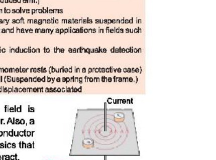
Definition "A magnetic field is produced around a current-carrying conductor. Also, a changing magnetic field gives rise to a current in a conductor placed in it. Electromagnetism is a key area of physics that studies how electric charges and magnetic fields interact."
In 1820, Hans Christian Orstad found that electricity and magnetism are correlated.
Electromagnetism is crucial for modern technology, including phones, computers, and medical devices. In this chapter, we will explore basic concepts like electric fields, magnetic forces, and electromagnetic induction, and see how these principles affect both natural phenomena and technology. Understanding these concepts help us appreciate how electromagnetism influences our world and drives innovation.
Magnetism started with lodestone, a natural mineral discovered in ancient Turkey. Lodestone, or magnetite (Fe3O4), can attract metals like iron and steel and aligns with the Earth's magnetic poles, leading to the invention of the compass.
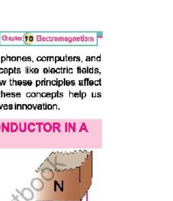
Force on a current-carrying conductor in a uniform Magnetic field
Let us now determine the magnitude of the force on a current-carrying conductor placed inside a magnetic field. Experimentally, it has been observed that the magnitude of the force acting on the conductor is directly proportional to the current I in the conductor, the length L of the conductor, and the strength of the external magnetic field B.
Mathematically
F ∝ I ----------- (i)
F ∝ L ----------- (i)
F ∝ B ----------- (iii)
Combine (i), (ii) and (iii). We have
F ∝ BIL
F = kBIL
In SI units, the value of k = 1. Therefore,
Thus, the force F on a conductor of length L, carrying a current I and placed perpendicular to a magnetic field of strength B, is given by
F = BIL ----------- (iv)
is required expression for the force acting on current carrying conductor placed in uniform magnetic field.
From Eq. (iv) we can see that B = F/(IL)
Magnetic induction / Strength of magnetic field
The strength of the magnetic field is also known as the magnetic induction B, which has the same direction as the field. The magnetic strength is numerically equal to the force exerted on a conductor of length one metre carrying one ampere current, placed perpendicular to the magnetic field.
Equation B = F/(IL) also gives us the unit of B, the SI unit of B is tesla (T).
1T = 1 N A-1 m-1
(SI unit of B, Nature of B)
It may be noted that magnetic induction is a vector quantity. Its direction is that of magnetic field.
Direction of L
We can also consider a vector L which has a magnitude equal to the length of the conductor and its direction is along the flow of current. When L makes an angle θ with B
Now consider a conductor L placed at an angle 'θ' in the magnetic field, then we will use the component of L perpendicular to B i.e., (L sinθ), as shown in Fig. Then the Eq. (1) will become.
F = BIL sinθ --------- (2)
In the vector form the Eq. (2) can be written as
F = IL × B ------------- (3)
Maximum Force
Equation (2) shows that the force will be maximum (BIL) when the conductor is perpendicular to the field, i.e., θ = 90°.
Minimum Force
Force will be zero (minimum) when the conductor is along the field i.e., θ = 0.
Determination of direction of force
Method-I
It has been observed experimentally that a current-carrying conductor placed in a magnetic field experiences a force. Consider a straight conductor carrying a steady current placed perpendicular to uniform magnetic field. Assume the direction of the current is out of the paper as shown by ⊙ in Fig. The direction of magnetic field produced by the current is also shown.
Just as two magnets exert forces on each other through their magnetic fields, a current-carrying conductor experiences a force due to the interaction between its own magnetic field and the external magnetic field. To determine the direction of this force, consider the interaction between the two fields.
The magnetic field produced by the current and the external uniform magnetic field reinforce each other on the right side of the conductor and cancel each other on the left side. Consequently, the conductor moves towards the side where the field is weaker. That is, the force on the conductor is directed to the left. Thus, the force F is perpendicular to both the conductor and the magnetic field.
Method-II
Fleming's left-hand rule is used to predict the direction of the force experienced by a current-carrying conductor in a magnetic field. To apply the rule:
Fleming's Left-hand Rule
Position your left hand such that the first finger points in the direction of magnetic field, the second finger points in the direction of current, the thumb will then point in the direction of force.
Method-III
However, direction of force can also be found by using right hand rule of vector product that can be stated as:
Right hand rule
Curl fingers of your right hand from current to magnetic field through small angle, the stretched thumb will indicate the direction of force.
Magnetic Flux and Flux Density:
"Number of magnetic field lines passing normally through a surface is known as magnetic flux"
(OR) Mathematically magnetic flux is a scalar product of magnetic induction and vector area of the surface. The magnetic flux through a plane element of vector area A in a uniform magnetic field is as:
φB = B.A
or
φB = BA Cos θ
S.I unit of magnetic flux is Weber (Wb) or NA-1 m.
Special Cases
Case 1
When vector area A and magnetic induction B are in the same direction, then maximum flux passes through the surface is given by:
φB = BA cosθ
φB = BA cos 0°
φB = BA
Which is the maximum value of the flux.
Case 2
When vector area A of the surface and B are perpendicular to each other, i.e. θ = 90°
φB = BA cos 90°
φB = 0
Which is the minimum value of flux.
Flux Density Flux passing through unit area normal to the surface is known as flux density.
Flux density B = φB/A
as φB = BA cosθ
B = φB/(A cos θ)
If surface is placed normal to the direction of magnetic field, then angle between area vector A and B is zero, therefore
B = φB/(A cos 0°)
B = φ/A
Unit
φ = B.A ( , θ = 0°)
= N.m²/A.m = Nm A-1 = lweber (Wb)
Hence magnetic induction and Flux density are identical quantities. S.I unit of flux density is Wb m-2 or Tesla (T). Flux density is a vector quantity.
Flux through curved surface
In case of a curved surface placed in a uniform magnetic field, the curved surface is divided into a number of small surface elements, each element being assumed plane and the flux through the whole curved surface is calculated by the sum of the contributions from all the elements of the surface using Eq. φB = BA cosθ
Flux | Flux Density
-----|-----
• Total number of lines of force passing through a certain area is known as flux. | • Total number of lines passing through a unit area, if area is perpendicular to the magnetic field lines.
• It is represented by φc | • It is represented by B
• φc = B.A | • B = φc/A , if θ = 0°
• Its SI unit is Wb | • Its SI unit is Wb m-2 or Tesla.
Magnetic flux linkage is a key concept in electromagnetism, particularly in the study of inductance and electromagnetic induction.
Definition "Magnetic flux linkage refers to the product of the magnetic flux through a coil and the number of turns in the coil."
Explanation
It essentially measures how much magnetic flux is linked with the coil due to its multiple turns, and is an important factor in understanding how coils and inductors operate in electrical circuits.
Magnetic flux linkage = φ = N φB
Where φB is the magnetic flux through a single loop of area A and N is the total number of turns of the coil.
Importance
Magnetic flux linkage plays a crucial role in the design and operation of transformers, electric motors, generators, and inductors. This concept is particularly important in Faraday's law of electromagnetic induction.
A current-carrying conductor placed perpendicularly in a uniform magnetic field experiences a force F. Since a current is the flow of electric charges.
Experiments show that a charged particle does experience a force when it moves across a magnetic field. We can calculate thisforce by examining the behaviour of a current-carrying conductor in a magnetic field.
Derivation
Consider a conductor of length L, through which N charged particles, each with charge q, are passing in time t. The motion of these charged particles produces a current I in the conductor, which is given by
I = Q/t = Nq/t --------- (1) Q = Nq
where Q is the total charge flowing in time t. If v is the velocity of charged particles, then the velocity of the particles along the conductor is
v = vL
Where L is the unit vector in the direction of the current.
• The sign of the force depends on whether the charge q is positive or negative.
• However, the unit vector L is directed along the direction of the current, which is the direction of motion of positive charges. Since the particles take time t to move across the conductor of length L, therefore,
t = L/v (using t = S/v)
Put in q (1)
Then I = Nqv/L --------- (2)
If this conductor is place in a uniform magnetic field B, it will experience a force F, as given by
F = I L × B -------- (3)
As L = L L
Substituting the values of I and L in Eq. (3) we have
F = (Nqv/L) (L × B)
or F = Nqv L × B ---- (4)
As velocity v is directed along the conductor L, so L = v
F = Nq v × B
Therefore, the force on a single particle will be
F = q v × B --------- (5)
If θ is the angle between B and v, then magnitude of force F is given by
F = q v B sinθ --------- (6)
Maximum Force
Therefore, the force is maximum when B is perpendicular to v, i.e., θ = 90°
Minimum Force
Force is zero when B is in the direction of v, i.e., θ = 0.
Direction of Force
The direction of force can be known by applying Fleming's left-hand rule or right-hand rule.
(a) For positive charge (q = + e)
The positively charged particle enters into the magnetic field along the dotted line on plane of paper. It experiences a force in the upward direction due to which it is deflected along a curved path (Fig. a).
F = + e v × B
(b) Fo negative charge q = − e
The negatively charged particle is deflected downward by the force acting on it downwards (Fig. b).
F = − e v × B
Definition
A velocity selector is a device used to determine the velocity of a charged particle. In this device, electric and magnetic forces are applied to the moving particle in such a way that they balance each other only for one value of velocity, allowing the particle to continue moving with a constant velocity.
Explanation
• Consider a particle with a positive charge +q that enters a uniform magnetic field B at a right angle to it, with a velocity v.
• The magnetic force acts on the particle in the upward direction, as shown in Fig.
• To balance this magnetic force, an electric force must act downward on the particle.
Construction
A velocity selector consists of a cylindrical tube located within a magnetic field B. Inside the tube is a parallel plate capacitor that creates a uniform electric field E. The electric field E is oriented perpendicular to the magnetic field B, as shown in Fig.
Working
• When the charged particle enters the left end of the tube, the magnetic force acts upward, while the electric force acts downward in the direction of the electric field E on the positively charged particle.
• If the strengths of the electric and magnetic fields are adjusted appropriately, these forces will cancel each other out.
• With no net force acting on the particle, its velocity v remains constant in accordance with Newton's first law.
• As a result, the particle moves in a straight line at a constant velocity and exits the right end of the tube.
• The particles with velocities different from v will be deflected and will not exit at the right end of the tube.
• The magnitude of the velocity selected can be determined as below. As the velocity v is perpendicular to both B and E, therefore,
Magnetic force (upward) = Bqv
Electric force (downward) = qE
For no deflection of particle Bqv = qE
or v = E/B
Motional e.m.f.
Def: "The e.m.f. induced across the ends of the conductor due to its motion in the magnetic field is known as motional e.m.f"
Explanation:
Consider a conductor of length 'L' placed in a uniform magnetic field on the copper railings. The ends of the railing are connected with Galvanometer The magnetic field is applied into the plane of the paper. When the conductor is dragged in a magnetic field, the charge inside the conductor is also dragged with the same velocity. The moving charge in a magnetic field experiences force given by:
F = q(v × B)
Because conductor is moving perpendicular to the field therefore θ = 90° hence
F = qvB sin90°
F = qvB -----------(1)
The direction of the force on charge particle is determined by right hand rule and its direction is as shown in fig. This force will drive the charges in the conductor from end A to B. Therefore, the top end of the conductor will become positively charged and its lower end become negatively charged. Thus, the potential of end 'b' will increase whereas the potential of the lower end 'a' conductor due to negative charge will fall. The Potential difference across the ends of the conductor will maintain flow of electric charge or current in the external circuit.
Expression:
Due to this Potential difference an electric field will exist along the conductor whose direction is downward. The force on the charge due to the electric field is given by:
Fe = qE ---------- (2)
When a steady or constant current is established then the electric and magnetic forces balance each other and charges are in equilibrium. Therefore
qE = q vB
E = Bv -----------(3)
If the potential difference across the wire is Vb - Va ΔV then
E = -ΔV/Δr
Or ΔV = - EΔr
Where Δr = L
Vb - Va = - BvL
Where Vb - Va is also motional emf because it lasts as long as wire is moving in the magnetic field. It is also represented by ε
ε = - BvL -----------(4)
If conductor is moving such that its direction makes an angle 'θ' with field the emf is written as
ε = - BvL Sinθ ------(5)
The charge in the external circuit move from point 'b' to point 'a' thus decreases the electric field intensity E and so does the electric force. Hence equilibrium inside the wire is disturbed in the favour of magnetic force which will make the charge to move from 'a' to 'b'.
Faraday's Law and Induced emf:
Statement:
The average emf induced in a conducting coil of N loops is equal to the negative of the rate at which the magnetic flux through the coil is changing with time.
Explanation:
Consider a conductor AB placed over a copper railing. The magnetic field is applied perpendicular to the direction of motion of a conductor. Let x1 is initial position of conductor. After Δt sec its position is given by x2.
Let Δx is the distance covered by the conductor in time Δt sec. Velocity of the conductor is written as:
v = Δx/Δt
The motional emf across the ends of conductor is given by:
ε = - BvL.
Substituting the value of v
ε = -B (Δx/Δt) L
Where Δx × L is change in area of the closed circuit or loop.
As Δx × L = ΔA
ε = - B∆A/∆t ---------- (1)
By definition of magnetic flux
φ = B. A
The magnetic field is uniform therefore the change in magnetic flux is due to change in area of the closed circuit. i.e.
Δφ = B∆A
Therefore Equation (1) can be written as
|ε=-Δφ/Δt|
It is the mathematical form of Faraday's law of Electromagnetic induction when a coil has 'N' turns the induced emf is written as:
ε = - N Δφ/Δt
The minus sign indicates that the directionnof the induced emf is such that it opposesthe change in flux.
Statement
"It states that the direction of induced current is always so as to oppose the change which causes the current."
Explanation:
Let us apply the Lenz's Law to the coil in which the current is induced by the movement of the magnet. We know that the current in the coil produces magnetic field which is similar to bar magnet. One end of the coil act as a north pole and the other south pole. If the coil is to oppose the motion of the bar magnet, the face of the coil toward the magnet must be a north pole, this arrangement causes the two north poles to repel each other. If it is to happen, the current in the loop must flow in anti clockwise direction. According Lenz's law, the push of magnet is change that produces induced current and field due to this induced current opposes the bar magnet. When the magnet is pulled away from coil, the induced current opposes the pull by creating a south pole on the face of coil towards the magnet.
Lenz's law and Law of conservation of energy:
Lenz's law is also a manifestation of the law of conservation of energy and can be conveniently applied to circuits involving induced currents. To understand this let us revisit the experiment depicted. Consider a rod moving on two conducting rails to the right side then emf induced will produce a current in it in anticlockwise direction. When current carrying rod is moving in the magnetic field, it experiences a magnetic force Fm. Its magnitude is given by:
Fm = ILB sin 90°
By right hand rule, the direction of Fm is opposite to v. So it will oppose the motion of the conductor and will tends to stop it. An external dragging force equal to the Fm, but opposite in direction is applied to keep the conductor moving with uniform velocity. This dragging force provides the energy for induced current to flow. This energy is the source of induced current thus electromagnetic induction is according to law of conservation of energy.
The Lenz's law forbids the induced current to flow in clock wise because force Fm will be directed in the direction of velocity v that would accelerate the rod to the right side and it would induce the stronger current. Thus the current is induced in the circuit without expending energy. The wire will be accelerated more and more and this process will become self-perpetuating, which is against the law of conservation of energy.
Factors Affecting e.m.f.
i. Rate of Changes of Magnetic Flux
Faraday's law suggests that faster changes in magnetic flux result in greater induced emf.
ii. Number of Turns of the Coil
According to faraday's law, induced emf is also proportional to the number of turns of the coil. More turns result in a greater induced emf.
iii. Relative Speed
The speed of the coil (or conductor) through a magnetic field also affects the magnitude of the induced emf. Faster speed increases the rate of change of magnetic flux that results into an increase in the induced emf.
Ferrofluid is a unique material that exhibits both liquid and magnetic properties. It operates through a combination of magnetic and fluid dynamics principles. Essentially, the ferrofluid is a colloidal suspension of magnetic particles in a carrier fluid (such as oil or water).
Explanation:
(i) Nanoparticles
Typically, the magnetic particles are iron oxide, ground to the nano-scale and approximately 10 nanometres in size.
(ii) Stable suspension
These particles are coated with a surfactant, a substance that reduces surface tension. This coating prevents the particles from clumping together, ensuring they remain evenly dispersed in the fluid. The viscosity of the fluid, the nanometre size of the particles, and their constant movement prevent the particles from settling down.
(iii) Magnetic Properties
When there is no magnet around, a ferrofluid acts like a liquid, but when there is a magnet nearby the particles are temporarily magnetized and the fluid becomes a magnet. They form structures within the fluid causing the ferrofluid to act more like a solid. When the magnet is removed, the particles are demagnetized and the ferrofluid acts like a liquid again.
(iv) Forces acting on ferrofluids
This phenomenon is due to the competition between magnetic forces, surface tension and gravity. In the presence of strong magnetic field, the formation of chain-like structures is a result of magnetic forces pulling the fluid upwards while gravity and surface tension work to pull it back down. These chains align along the magnetic field lines and increase the viscosity, making it behave like a solid bulging in certain directions. These are commonly known as spikes. However, the spikes are formed where the magnetic forces overcome the other forces. The following experiment will exhibit this phenomenon.
Experiment:
You need some laser printer toner, some cooking oil, test tube, a glass bottle, a small stick and a magnet.
Procedure:
Pour some toner in the test tube. Remember that laser printer toner contains 40 % iron oxide in nanometre particle size. Add some cooking oil in it and mix it well with the stick to form ferrofluid. Put this fluid in the bottle. The fluid will act like a liquid on shaking the bottle. Now bring the magnet near to fluid outside of the bottle.
You will observe that the fluid jumps towards the magnet, because it has itself become a magnet. If we hold the magnet on the side of the bottle, you will see a structure with spikes formed by the fluid as shown in Fig.
Applications of Ferrofluids:
There are many applications of ferrofluids in the fields of electronics, medicine, engineering, and active research in Physics and Material science.
i. In electronics, ferrofluids are used in rotary seals for computer hard drives and other rotating shaft motors. In loudspeakers, ferrofluids are used to cool the voice coil which can heat up during operation. The magnetic field holds the fluid in place around the coil, allowing it to absorb and dissipate heat more effectively. Ferrofluids are also used in speakers to dampen vibrations and improve sound quality.
ii. In medical applications, ferrofluids can be directed to specific areas in the body using external magnets, allowing for targeted drug delivery. The magnetic particles can carry drugs directly to a tumor or other targeted site, reducing side effects and improving treatment efficiency. Ferrofluids can also be used as contrast agents in magnetic resonance imaging (MRI).
iii. Other applications of ferrofluids include damping or precisely controlling the flow ofliquids by manipulating the magnetic field.
A seismometer is an instrument that responds to any movement of the rocks under the ground or vibration caused by earthquakes, volcano eruption and explosion.
Principle:
A seismometer detects earthquakes by using electromagnetic induction to convert ground motion into electrical signals.
Working:
A seismometer includes a weight suspended by a spring. When an earthquake occurs, the ground moves but the weight tends to stay stationary due to inertia. This results in relative motion between the weight and the frame of the seismometer which is attached to the ground. The weight is often attached to a magnet whichmoves inside a coil of wire Fig. This setup works according to Faraday's law of electromagnetic induction, that is, the changing magnetic flux through the coil induces an emf in the coil. This gives rise to an induced electric current.
Output Signal:
The induced current is proportional to the velocity of the ground motion. The electrical signals generated are then amplified and recorded. Thus, data is provided onthe amplitude, frequency and the duration of the earthquake waves.
Data Analysis:
The data is analyzed to determine various characteristics of the earthquake, such as location,magnitude and depth.
Experimental Setup:
Usually, a seismometer is buried under the ground at a depth of 50-1000 metres. It is placed in a protective case called a vault. This is a cylindrical steel tank that is approximately 1 metre wide and 2 metres deep with a concrete pad at the bottom Fig.
More figures from this unit